In this tutorial, you will learn SolidWorks surface modeling. Lofted surfaces can be used to create smooth, complex shapes using the simple tools provided by SolidWorks. Lofted surface are a good introduction to surface modeling techniques. You can use this technique as a first step to create parts with smooth curves, such as water bottles, bicycle frames, and aesthetic plastic components for consumer products.
In this example, we will be creating a simple loft, which could be used as the basis for the creation of a product such as a plastic vase. Let’s get started!
What will you learn?
You will learn the following techniques in this tutorial. If you are interested in a specific technique, you can click on the links below.

[toc]
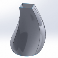
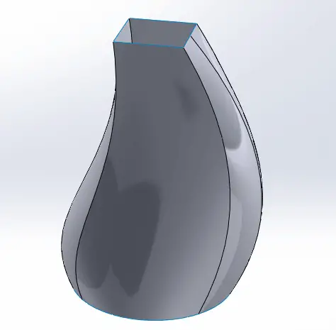
The final design we will create is shown below:
Creating the Initial Sketch
The basis for our design will be a set of sketches which will define our Surface Loft feature. Let’s begin by creating the first sketch.
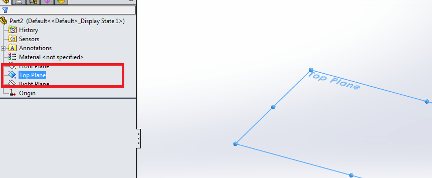
Select the Top Plane.
Now, let’s sketch a circle with a diameter of 5 inches.
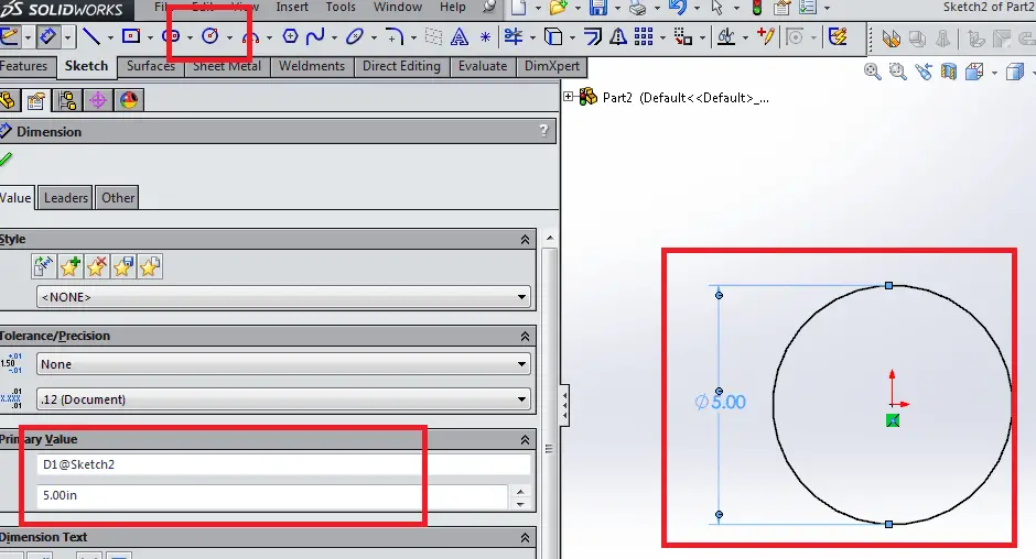
Select OK and exit the sketch.
Creating a Reference Plane and Sketch
With our first sketch created, we will now create a second plane on which to sketch the second profile of our lofted surface.
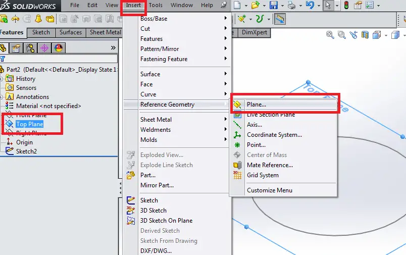
Select the Top Plane.
Now select Insert > Reference Geometry > Plane …
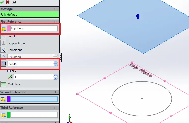
We want to create a plane that is parallel to the Top Plane, offset at a distance of 8 inches. So, we will input “8” into the First Reference “Offset Distance” box. Select the green check mark again to complete the Reference Plane.
Now, let’s use the new plane to create a second sketch, which we’ll use to define the end of our loft.
Select the new Plane that you just created. (Note – you can choose to hide and show reference geometry, such as Planes, by selecting View > Planes.)
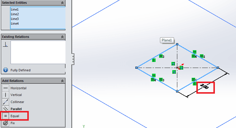
On this plane, sketch a square with each side a length of 2 inches. To control the sketch, create a center-point rectangle at the origin. Now dimension one side of the rectangle to 2 inches. Now, select each edge of the rectangle and constrain them using the “Equal” constraint on the left panel.
Select OK to exit the sketch.
Creating Guide Curves for SolidWorks Loft Tutorial
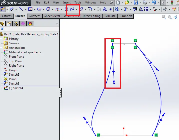
Now, we will create a set of guide curves to guide the loft between the two shapes we’ve just created. This will allow us to refine the loft shape we want to create. Select the Front Plane. Using the Spline tool, create a curve beginning at the first sketch you created on the Top Plane and ending at the second sketch you created on the Reference Plane.
Adjust the shape to your taste, using the mouse to drag the tangent control at either end of the sketch. When you have adjusted the sketch to look as it does below, exit the sketch using the green check mark.
Creating the Surface Loft
Now, select Insert > Surface > Loft
Select the two sketches you created, which should populate the “Profiles” box on the left pane.
Select the “Guide Curves” box and select each of the two guide curves you created, selecting the small green check mark each time.
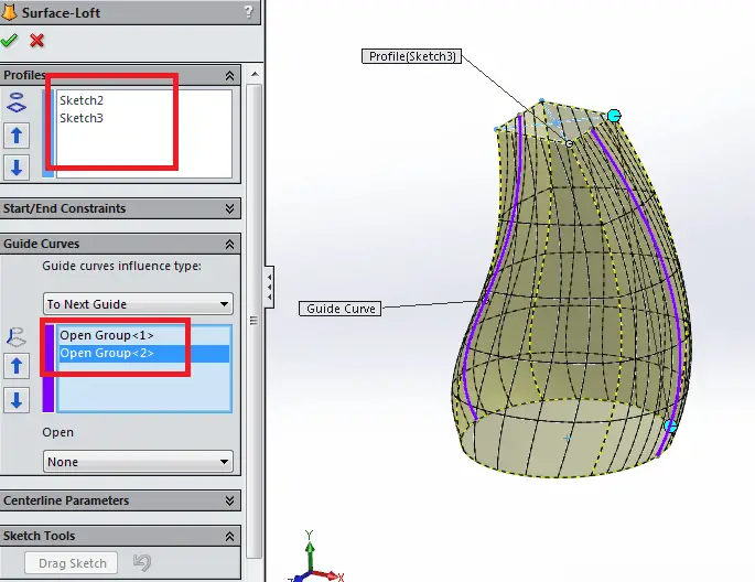
To complete the loft, select the green check mark in the upper left hand of the left pane.
Congratulations! You’ve created a simple Surface Loft which you can use as the basis for your design. This SolidWorks surface modeling tutorial is complete.
Final Thoughts
In this SolidWorks loft tutorial, you learned how to create a lofted surface. In addition, you also learned how to create a new sketch, how to create guide curves, and also the process of using the spline tool.
Check out other SolidWorks drawing tutorials and try another one!
Leave a Reply