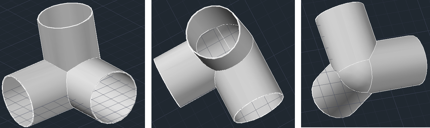
Here is how you can use AutoCAD to design this 3 directional “90 degree elbows joint”.
Let’s first look at what our figure is like in 2 Dimensions sketch.
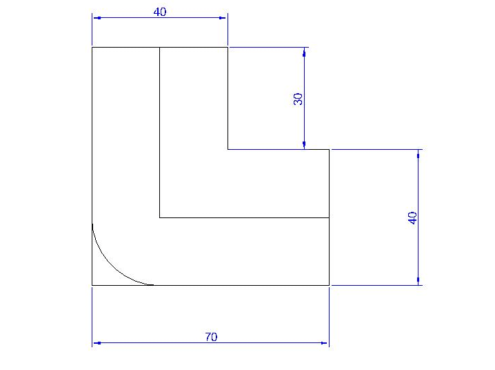

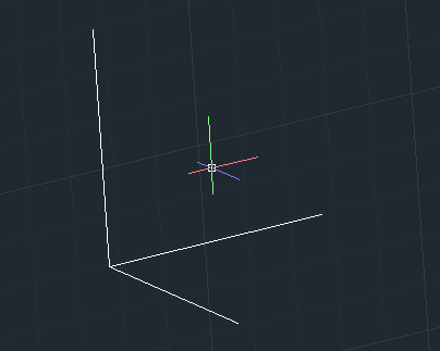
Step 1
Draw the 3 dimension figure below (looking like the Cartesian coordinate system x, y, z). Each of these lines should have a length of 50 and form 90 degree one with the two others.
Step 2
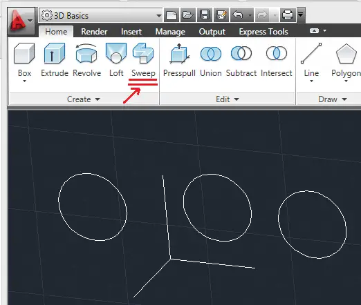
Draw 3 circles with radius 20. (Their location is not important, you can place them wherever you want in the drawing windows)
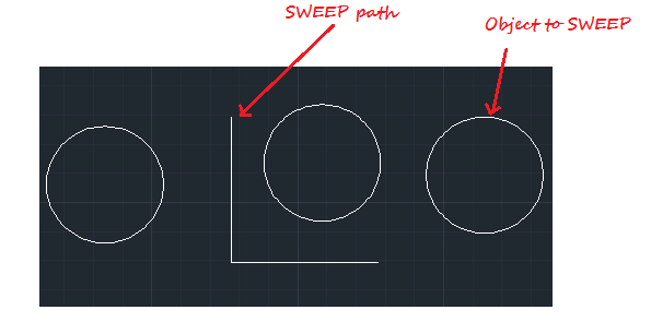
Step 3
Get on a 3D view, you need to be able to select the 3 path.
Step 4
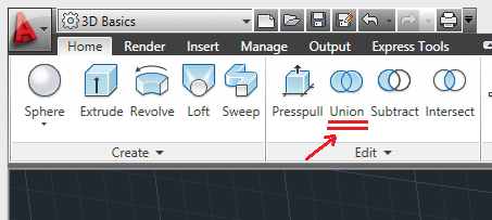
Use SWEEP. (Look at the figure right above to locate where SWEEP is)
- Click on SWEEP
- Select one circle
- Press ENTER on your keyboard
- Select a line
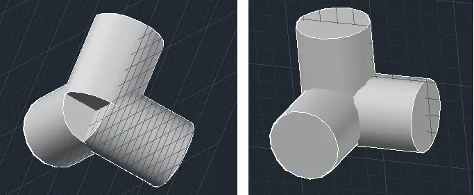
Do this 3 times, you should have the image below.
Step 5
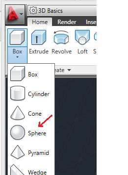
Draw a SPHERE of radius 20.
Step 6
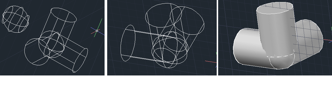
After drawing your SPHERE, move it and place such as it look like on the figure below. It looks a little difficult to achieve, but it is not. You have to take your SPHERE from his center and drop it at the Center of those cylinders on the side they all meet.
Step 7
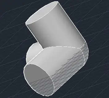
Use UNION to unite all together. Those 3 cylinders and the sphere should now form one and only object.
You should get something like this. All are now a single object.
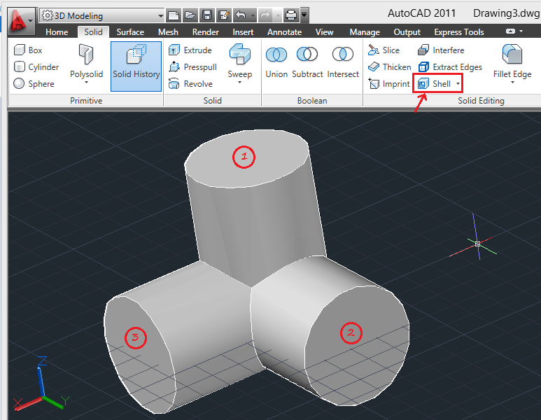
Step 8
Use the SHELL command.
- Activate the SHELL command
- Select the drawing
- Select now the faces 1, 2 and 3
- Enter 1 to denote the Shell Offset Distance
- And press ENTER on your keyboard
Result
You should get this.