In this demonstration, you will learn how to create customized holes in a solid object. SolidWorks software comes with a great tool which can be used to introduce different types of holes, such as counterbores, countersinks, drilled holes, straight taps, tapered taps and legacy holes. Hole Wizard provides a set of controls and options, for each of those hole types, which can be easily modified as any other SolidWorks feature. When you need to insert a specialized hole, you are recommended to utilize the Hole Wizard command rather than using the Extruded Cut option.
Launch Hole Wizard
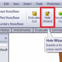
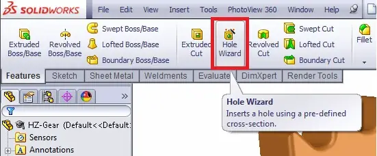
First, you have to create a solid part; Hole Wizard remains inactive as long as no 3d parts exist. To launch the Hole Wizard feature from the Feature Toolbar, click on the corresponding button as the figure below depicts.

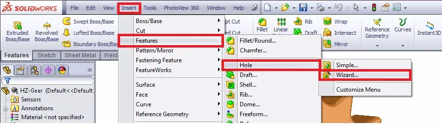
Depending on your SolidWorks software edition you can also start up this command by selecting Insert > Features > Hole > Wizard.
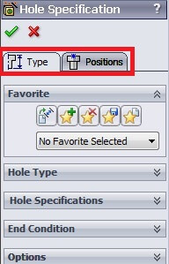
The Hole Wizard property manager shows up and you can now set the hole type options. On the upper side of this window you can find two tabs named Type and Positions. The Type tab can be used to introduce the hole type parameters whereas the Positions tab can be used for the holes placement.
Using Favorites
The Hole Wizard property manager provides a set of commands for utilizing hole styles that are to be reused several times. Under Favorites submenu you can find five buttons as illustrated in the figure below.
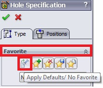
You can deselect any favorite option selected beforehand by hitting the first button (Apply Defaults / No Favorite). This option applies the default settings as well.
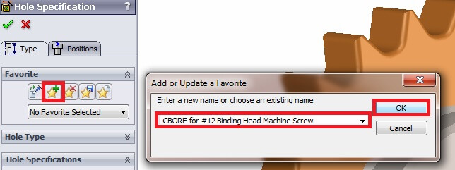
To add a favorite style or reset an existing one, click on the second button (Add or Update a Favorite). You will then be asked to type a name for your new style or to choose an existing name to update an existing style. Finally, hit OK to exit out of this process.
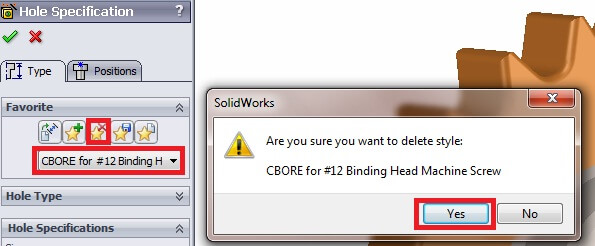
You can delete a favorite style by clicking on the third button (Delete Favorite), then selecting the name of the favorite style from the drop down menu and hitting Yes to finish this process.
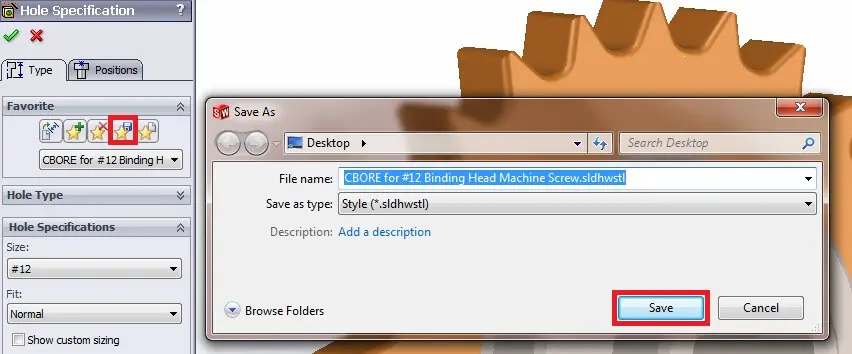
To save a favorite style click on the forth button (Save Favorite) and give the path and the file name you desire.
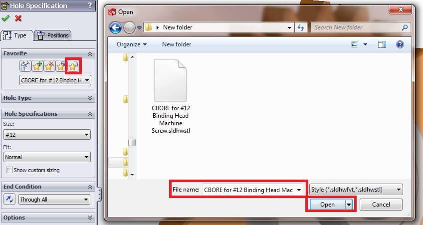
Finally, you can load a favorite style by clicking the fifth button (Load Favorite) and browsing the corresponding style from the path introduced beforehand.
Setting the Type of holes
The Hole Wizard feature provides a variety of hole types that can be imported within your parts. The figure below illustrates all six hole types that are available through this feature.
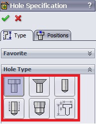
As it is previously mentioned the Hole Wizard hole types are the counterbores, countersinks, drilled holes, straight taps, tapered taps and legacy holes. The Hole Specifications, the End Conditions and the Options vary depending on the hole type you have chosen from the Hole Type submenu.

This picture above illustrates the Hole Specification options depending on the Hole Type that you have previously selected.
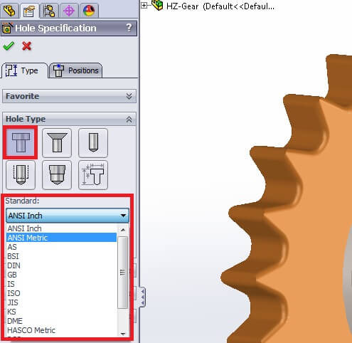
The next step in the procedure is to choose the Standard and the Type of the hole. SolidWorks provides a great number of Standards such as ANSI Metric, DIN, ISO etc.
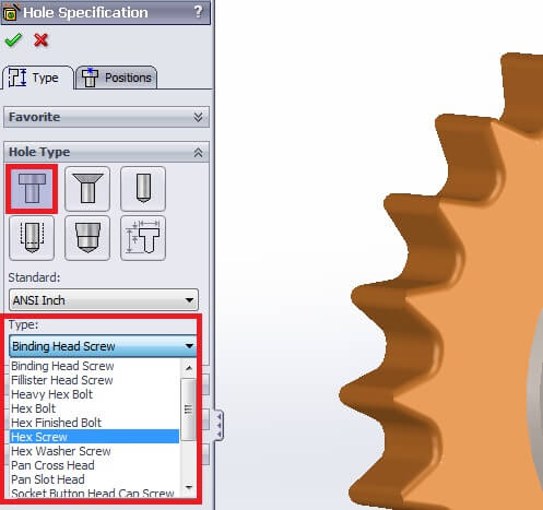
Depending on the Hole Type and the Standard introduced, you will find available the corresponding Types like Ηex Bolt, Hex Screw, Pan Slot Head and so forth.
Hole Specifications
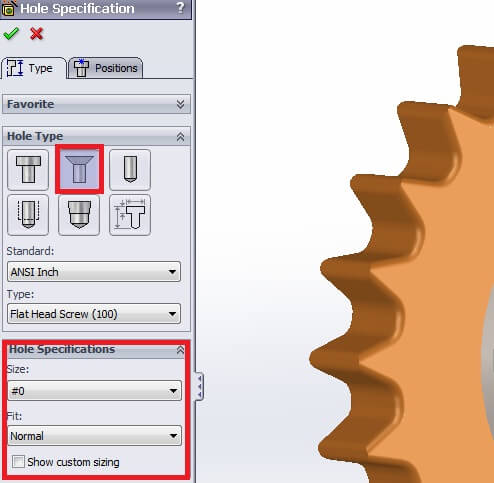
Once you are done setting the Hole Type item parameters, you will then move on to the next item of the property manager. The Hole Specifications submenu enables the users to import the desired Size and Fit of the holes that are to be created. From the Size drop down menu you can introduce the fastener’s size while the Fit drop down menu is used for the fastener’s fit selection (Close, Normal or Loose).
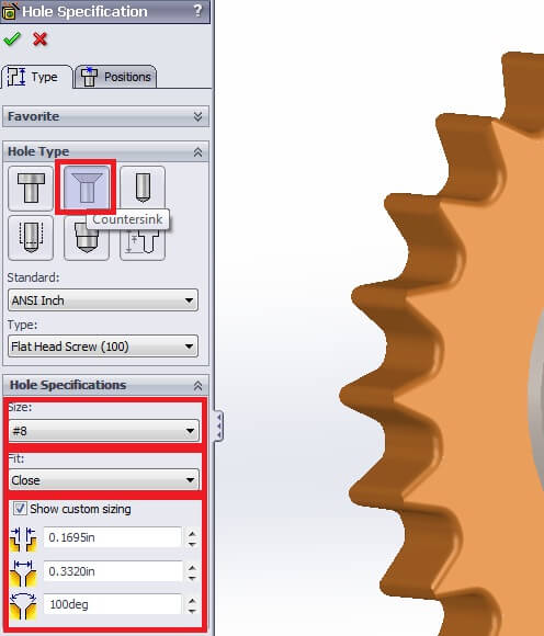
If you check the Show custom sizing box, the SolidWorks software will automatically load the relevant information from the database and you will see the estimated values of the Through Hole Diameter, Countersink Diameter and the Countersink Angle.
NOTE: It is essential to mention that the information provided under Show custom sizing option is strongly affected by the Hole Type selection.
End Condition
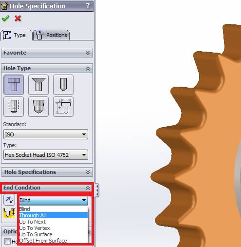
Next you will be asked to define the End Condition of the Hole Wizard holes, as you would if you were to insert an extruded cut feature. Therefore, if you want to place a blind hole you can choose Blind and set the Blind Hole Depth. You can insert a “through hole” clicking on the Through All option. An Up to Next, Up to Vertex or Up to Surface hole can be also created by choosing the corresponding option from the drop down menu and selecting the corresponding reference.
Positions
After completing the determination of the hole type and the hole specifications, you shall now define the hole positions. First, click on the Positions tab.
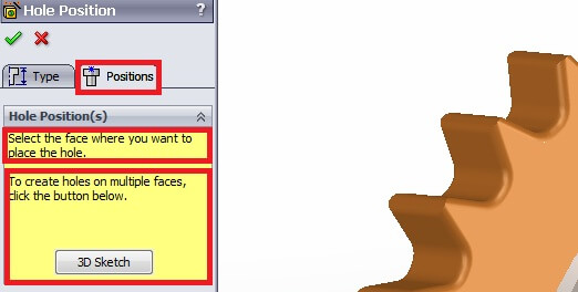
If you want to place a set of holes on a planar surface of this part, click on the desired part’s face. This action places you in a 2d sketch mode so you can add as many points (hole centers) as you need to by just clicking onto the desired locations.
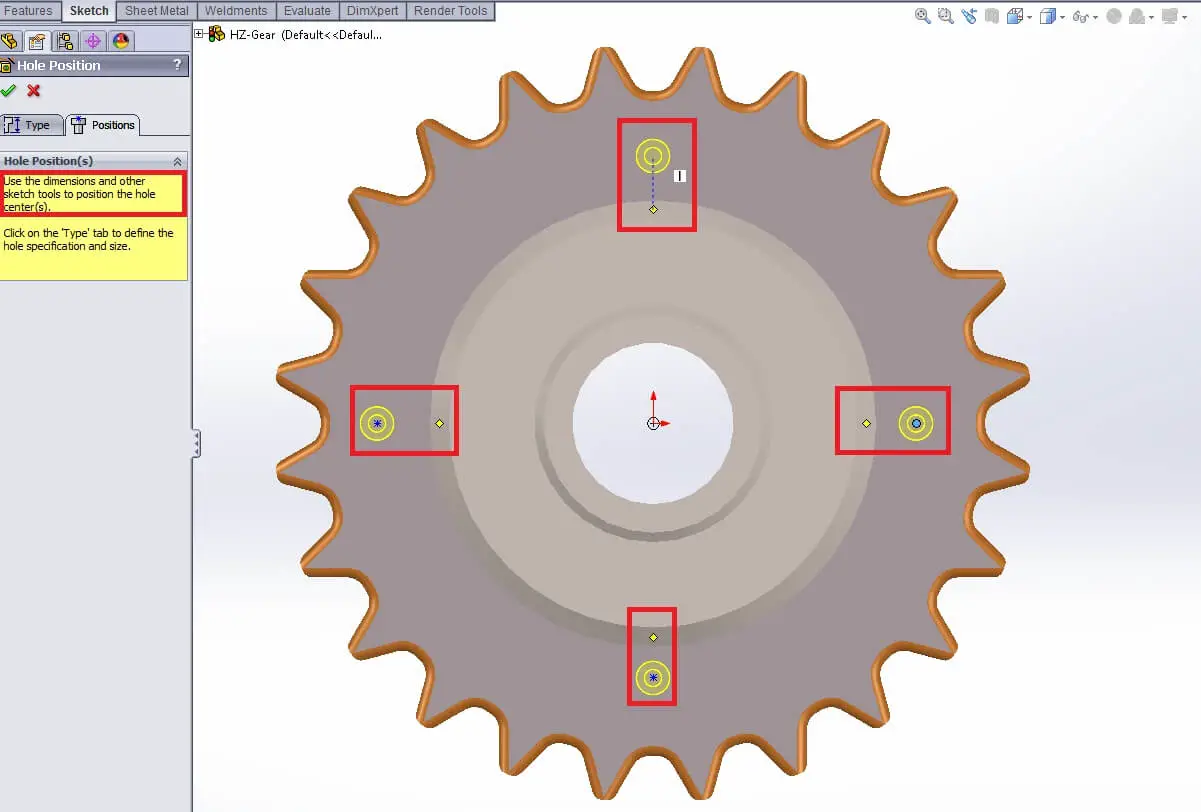
NOTE: Please notice that you are still in a 2d sketch mode, hence you can use the dimensions and any other sketch tools to precisely allocate the hole centers.
When you are done editing this sketch, you can hit OK to exit out of the process.
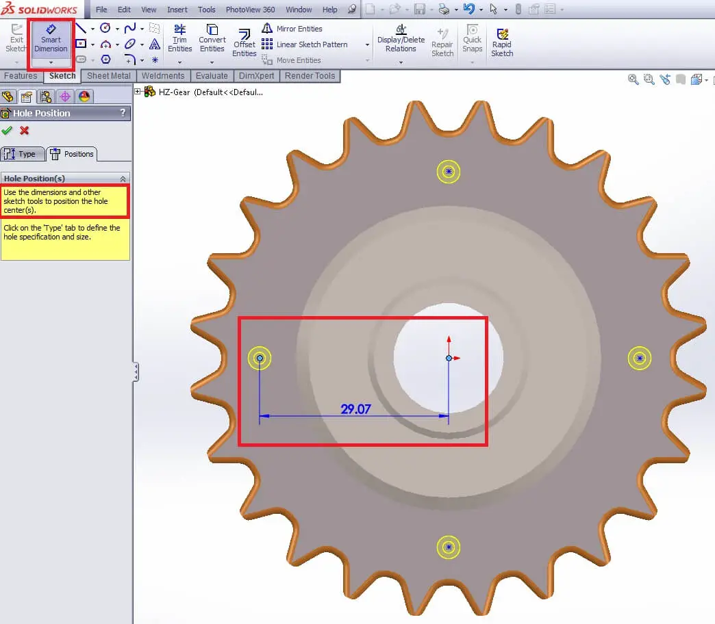
Tip: Before launching the Hole Wizard feature, you can create a 2d sketch that includes all of the desired locations (points) of the holes you want to insert. Consequently, you can utilize all the available sketch tools (Smart Dimensions, Relations and Constraints) to precisely allocate the holes positions.
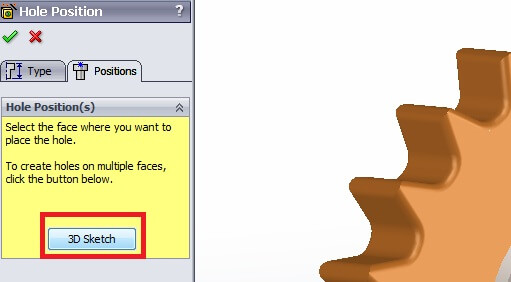
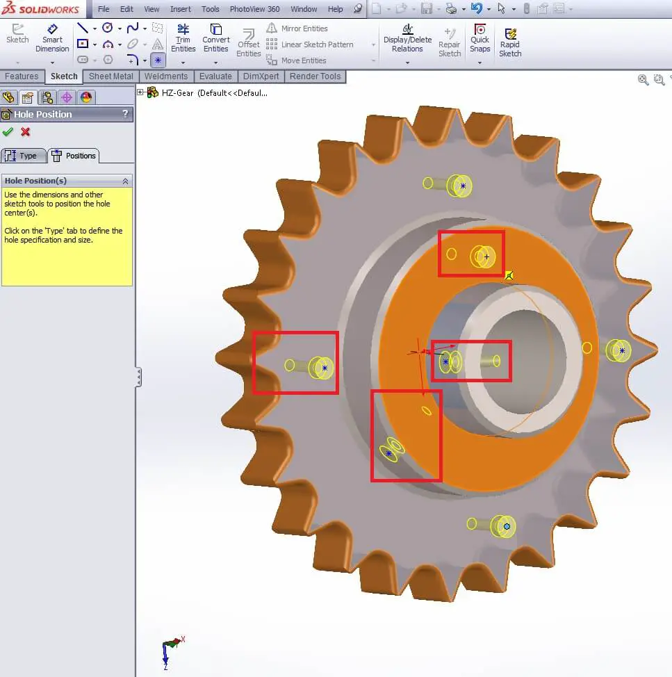
If you want to insert holes on multiple faces or even curved surfaces click on the 3D Sketch button. You are now placed in a 3d-sketch mode and the sketch point tool is pre-selected. You can add a set of holes on different planar or curved surfaces faces by just clicking on them. To constraint the hole positions hit the Escape key. You are still in 3d-sketch mode and you can now add dimensions, relations and so forth. Finally, click OK to finish this process.
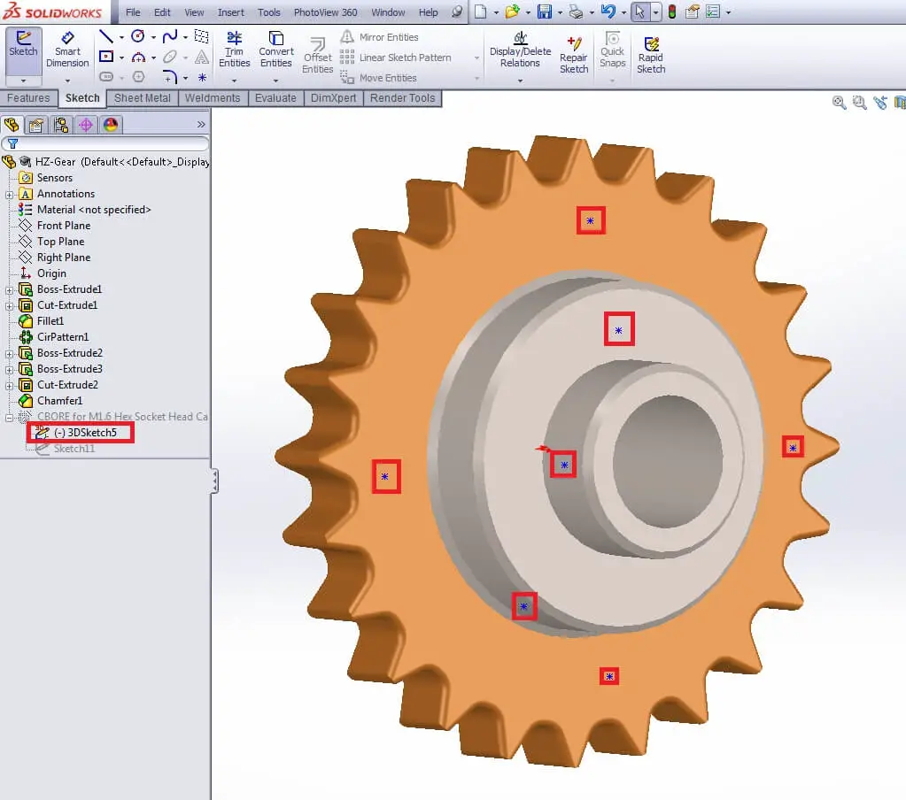
Feature Manager Tree
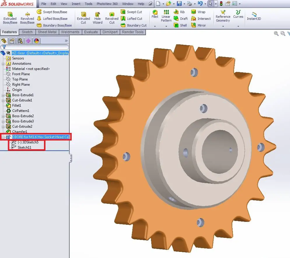
Expanding the Hole Wizard feature into the Feature Manager tree you will find two sketches. Within the first sketch, you will find the locations and the constraints of the hole centers. As any other SolidWorks sketch, you can simply edit this sketch by allocating again the hole positions, adding/deleting constraints and relations or even adding/deleting sketch points.
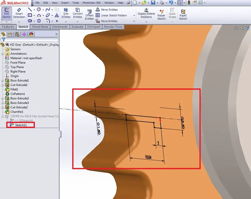
The second sketch of the Hole Wizard feature is the profile sketch. You are strongly advised not to edit this sketch. If you desire to edit the Hole Type options you can edit the Hole Wizard feature and introduce the new parameters.
Leave a Reply