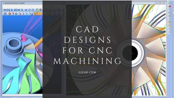
Computer-Aided Design (CAD) software has revolutionized the engineering and manufacturing industries, allowing designers to create complex 2D and 3D models with incredible precision and accuracy. Designing for CNC machining requires additional considerations to ensure that the design is optimized for the manufacturing process.
In this article, we will discuss ten pro tips to improve your CAD designs for CNC machining.
- Optimize Wall Thickness: Avoiding Excessively Thin Walls
One of the most important considerations when designing for CNC machining is the thickness of the walls. Thin walls can cause problems during machining, such as warping, distortion, or breakage. It’s important to maintain a minimum thickness to ensure that the part remains structurally sound. As a general rule, walls should be at least 1 mm thick, but the ideal thickness may vary depending on the material and the application.
- Design for CNC: Avoiding Features That Can’t be Machined
CNC machining experts from Machining Today said that some features are not good to go with, so it’s better if you can avoid such features. While CAD software can create complex designs with ease, not all features can be machined with CNC equipment. Sharp corners, overhangs, and other complex features can be difficult or impossible to machine with CNC equipment, leading to manufacturing problems or costly design modifications. To avoid these issues, designs should be modified to ensure that all features can be CNC machined.
- Precision and Practicality: Avoiding Excessive Tolerances
Tolerances are essential in engineering design, but over-tolerancing can increase the cost of manufacturing and may not improve the functionality of the part. Therefore, use tolerances only where they are necessary and keep them as tight as possible. This will help to reduce manufacturing costs and ensure that the parts meet the required specifications.
- Function Over Form: Avoiding Unnecessary Aesthetic Features
In most cases, aesthetic features do not add any functional value to the part. Unnecessary features can also increase the cost of manufacturing, as they require additional time and resources to machine. Therefore, it’s important to avoid these features unless they are essential to the design.
- Efficient Cavity Design: Accurate Depth-to-Width Ratios
Cavities are commonly used in engineering design to reduce weight and improve structural integrity. However, cavities with incorrect depth-to-width ratios can cause problems during machining, such as tool breakage or poor surface finish. To avoid these issues, ensure that the depth-to-width ratio is correct for the material being machined. A good rule of thumb is to keep the depth-to-width ratio at 4:1 or less.
- Improving Structural Integrity: Adding Radius to Internal Vertical Edges
Sharp internal vertical edges can cause tool breakage or poor surface finish. To avoid these issues, add a small radius to the internal edges. This will help to reduce stress concentrations and improve the overall quality of the part.
- Streamline Thread Design: Limiting Thread Length
Threads are commonly used in engineering design for joining parts or creating fasteners. However, threads can cause problems during machining, such as tool breakage or poor surface finish. Therefore, it’s important to limit the length of threads to minimize these issues. In general, threads should be no longer than three times their diameter.
- Large Enough to Manufacture: Avoiding Extremely Small Features
Extremely small features, such as small holes or intricate details, can be challenging to the machine and may not be necessary for the functionality of the part. Therefore, avoid these features unless they are critical to the design. In general, features smaller than 0.5mm should be avoided, as they can be difficult to machine accurately.
- Standardizing Holes: Designing Holes with Standard Sizes
Holes are a common feature in engineering design, but designing custom hole sizes can increase the cost of manufacturing and limit the availability of off-the-shelf parts. Therefore, it’s important to design holes with standard sizes whenever possible. Standard hole sizes are readily available and can help to reduce the cost of manufacturing by minimizing the need for custom tooling or additional machining steps. In addition, standard hole sizes are often used in conjunction with off-the-shelf components, making it easier to source parts for assembly.
- Clarity in Design: Avoiding Unnecessary Text and Lettering
Text and lettering can add clarity and improve the functionality of a design. However, excessive text or lettering can clutter the design and increase the cost of manufacturing. Therefore, it’s important to limit the use of text and lettering to only essential information. In addition, it’s important to use a legible font and ensure that the text is large enough to be easily read.
Conclusion
Designing for CNC machining requires careful consideration to ensure that the part is optimized for manufacturing. By following the ten pro tips outlined in this article, you can improve the quality of your CAD designs and reduce the cost of manufacturing. From maintaining appropriate wall thickness to designing cavities with accurate depth-to-width ratios, these tips will help you create designs that are easier to machine and produce high-quality parts that meet the required specifications.


Leave a Reply