
While a lot will give you many reason why AutoCAD is not the indicated software for 3D I want to deliver in this post the concept of 3D in AutoCAD and what you should be thinking about if 3D is a total new concept for you.
3D stand for 3dimensions right? so the most basic figure of the 3D concept is a cube, something like this:
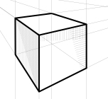

A cube is a 2D face extruded in a direction perpendicular to the 2D initial face with a specific dimension.
Any complex 3D object in simple definition is a combination of basic 3D object.
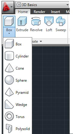
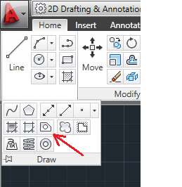
In AutoCAD, there are commands helping you create simple 3D objects with almost a click.
The 3D object included in this list are those shown in the figure below.
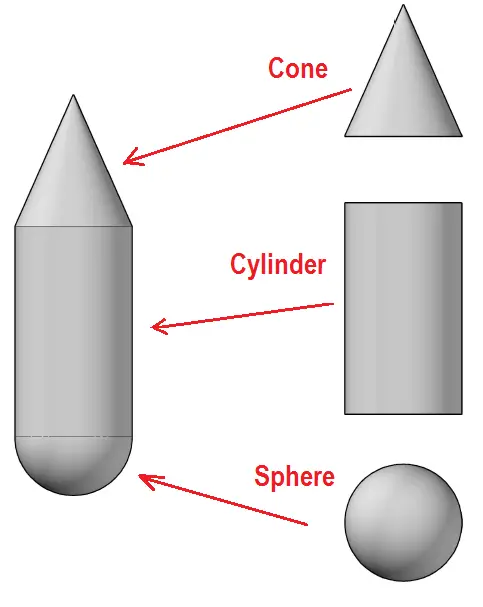
That being said, if we have a figure like the one following we can observe that is a combination of a sphere, a cylinder and a cone.
As true as it is that AutoCAD helps you quickly create some 3D object with a single command, it give you also the power to create them yourself with a combination of other command.
what is in here:
- The REVOLVE command in AutoCAD
- The REGION command in AutoCAD
- The EXTRUDE command in AutoCAD
- The SWEEP command in AutoCAD
- The INTERSECTION command in AutoCAD
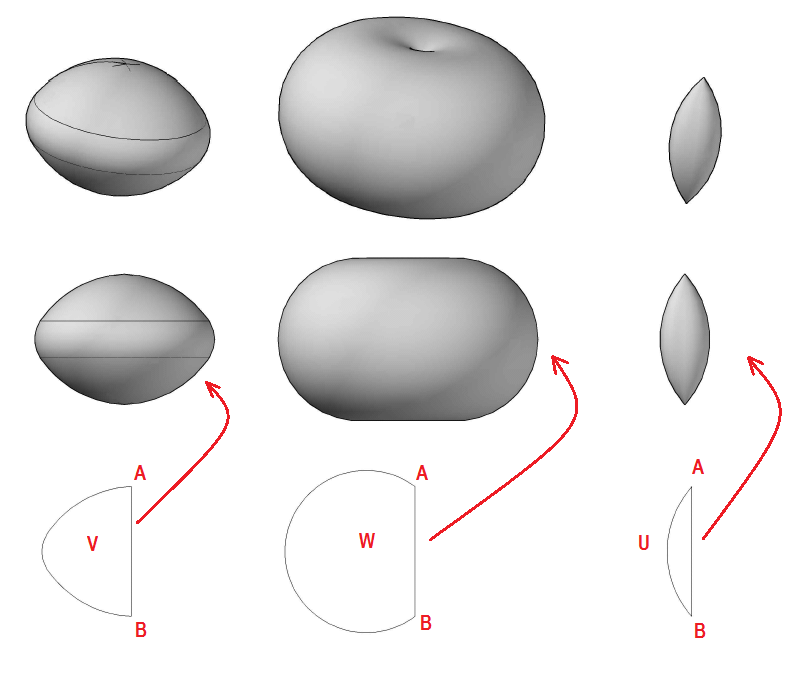
A sphere will be the figure at the extreme left revolved around the AB axis. To draw a Sphere using this procedure, you will need to use the REVOLVED command. From left to right, the original 2D figure is revolved around AB with 30, 200 and 360 degrees. To use the REVOLVE command, you will need a 2D face, the axis of revolution and the angle.

Using this principle, you can easily draw figures like the one below, where U, V and W are revolved around AB with an angle of 360 degrees.
The REVOLVE command is a frequently used 3D command in AutoCAD. You can also use it to obtain figure like this:
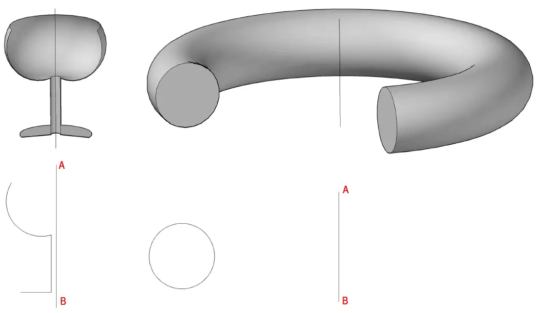
The “glass” is revolved with an angle of 220 degree (it would have been a complete glass if I had revolved it with an angle of 360 degree) and the torus is the circle revolved with an angle of 270 degree. As practice you can REVOLVE those 2 figures with 360 degree to notice the difference.
The difference brought by the REGION Command
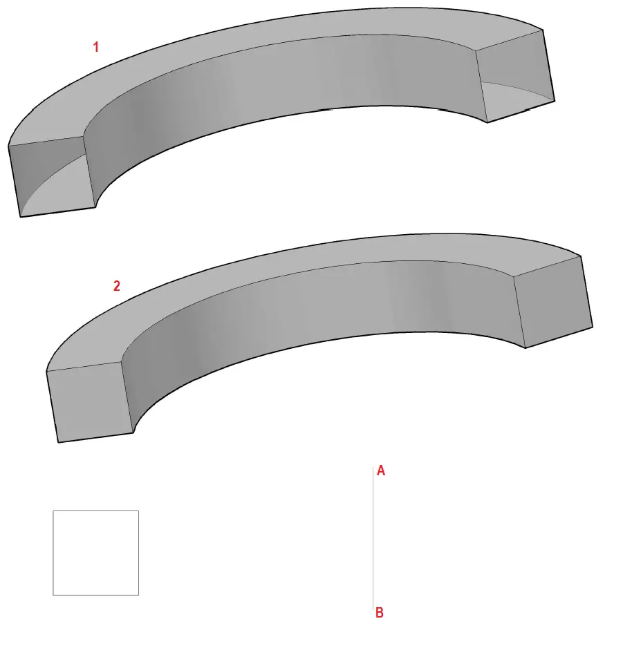
When using the REGION command on the 2D face before applying the REVOLVE command we obtain the difference below.
1 is the example without using the REGION command and 2 is the example using the REGION command on the square before applying the REVOLVE command. Notice here the REGION command help you obtain a full loaded solid as a result of the REVOLVE command.
While the REVOLVE command allows you go around an axis to get a solid, the EXTRUDE command help you obtain a 3D by extruding a 2D face along a line or along a path. To draw a cylinder without using the CYLINDER command, you can go like this:
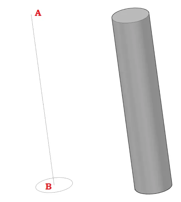
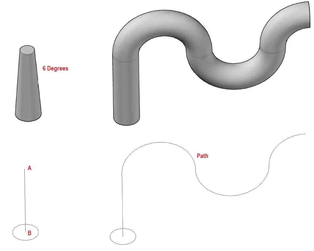
The EXTRUDE command helps you extrude along a path, and give you the ability to change angle of extrusion.
Down below, you have an extrusion of the circle with an angle of 6 degrees along the line AB. and an extrusion of the circle along a path.
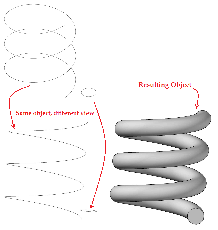
The SWEEP command works a bit like the Option of extruding along a path, but the SWEEP command does not care about the position of the 2D face. When you extrude a 2D face along a path, the base of the 2D face has to be orthogonal to the beginning of your path. This is not true when you use the SWEEP command. The SWEEP command will help you design figure like the one below.
Now let’s see what using these technique to build 3D objects and applying the UNION, SUBTRACT, and INTERSECT command help have complex 3D objects in AutoCAD.
You may need to have a look at how the SUBTRACT, and INTERSECT command work in AutoCAD.
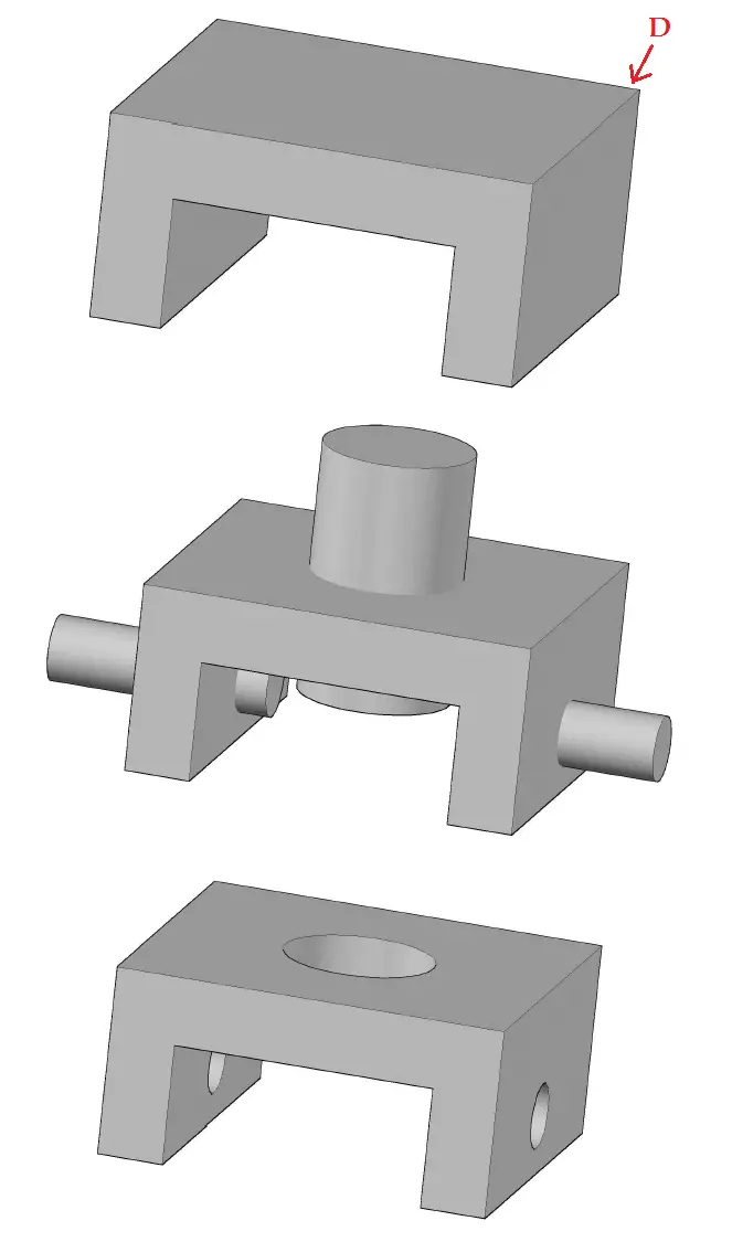
The SUBTRACT command help you subtract geometry from 3D object. Looking at the figure below, you can get D from extruding a figure looking like U upside down, and using 3 cylinders you can have 3 cylindrical holes on your primary design.
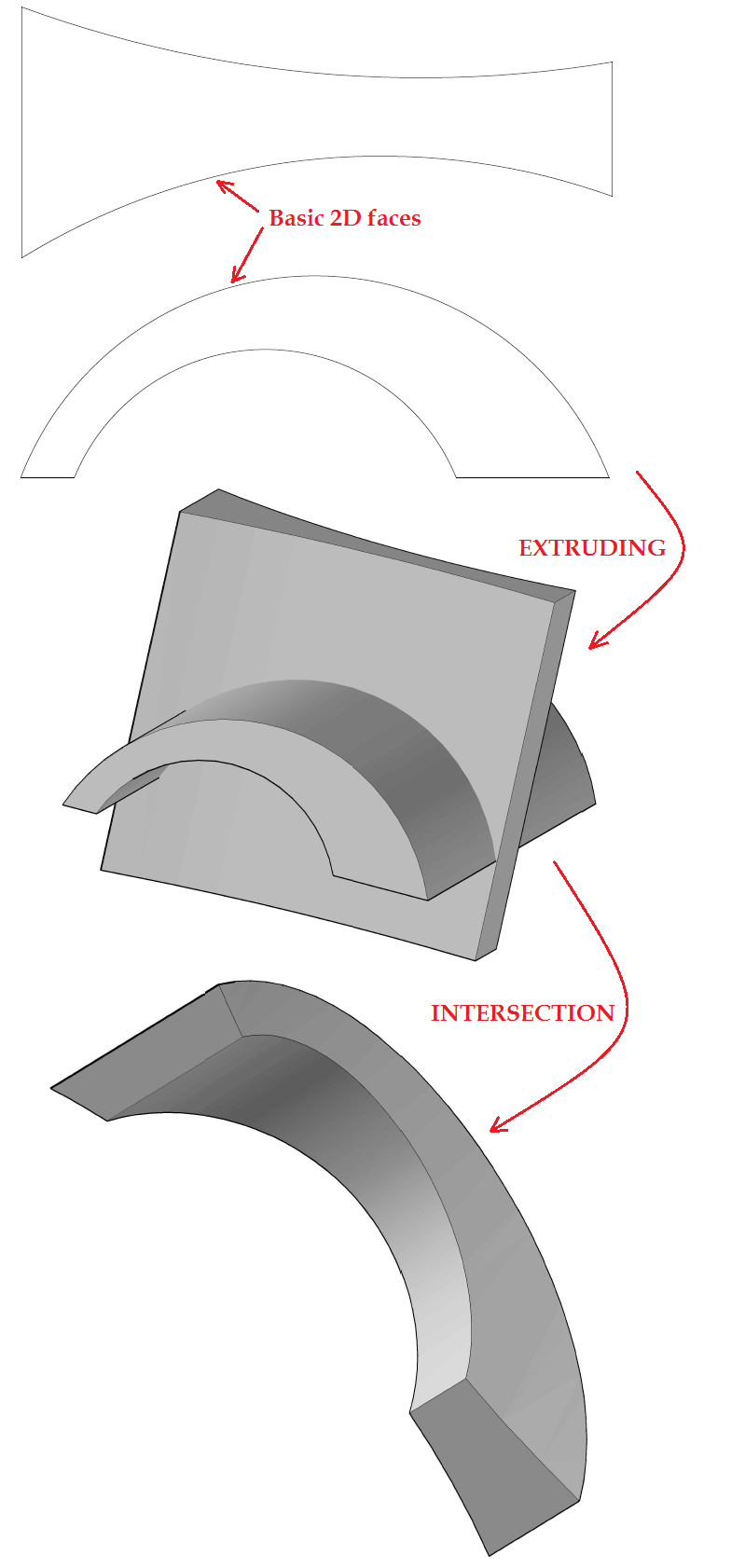
The INTERSECTION command gets the geometry common to 2 3D object in AutoCAD.
The example below shows two 2D faces that are extruded on 2 different planes in such a way the intersect perpendicularly and the INTERSECT command is used.
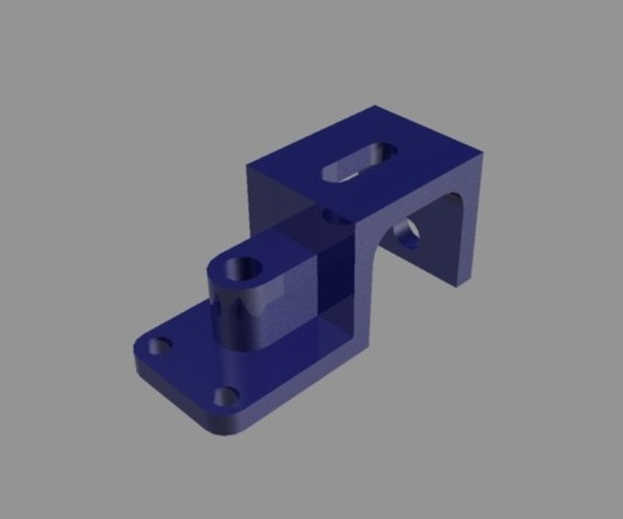
You have just learned main 3D commands in AutoCAD and should be able to design the following 3D object.
Comments
2 responses to “Basic Tools in 3D in AutoCAD”
[…] advanced surfacing capabilities in a much more effective manner. You check our 3D AutoCAD tips, tools, and […]
[…] the model in the viewer rotate between preset views – by default, these are Isometric and orthogonal views from SolidWorks or other CAD […]