Here is a simplified Microstrip antenna design with Ansys HFSS.
There are few basic things that must be known before designing an antenna in general such as:
The frequency range in which the antenna is planed to be be propagating, the size of the antenna, the material, the gain of the antenna and the structure of the antenna.

In this simple example, we will attempt to design a rectangular patch antenna with the following characteristic:
Resonant frequency between 1850-1990 MHz.
Transmission line impedance: 50 Ohm.
The dielectric constant of the substrate ξr = 11.9 (silicon)
Thickness of dielectric substrate (h) : 1.6 mm
Here is the Top view of Rectangular Patch
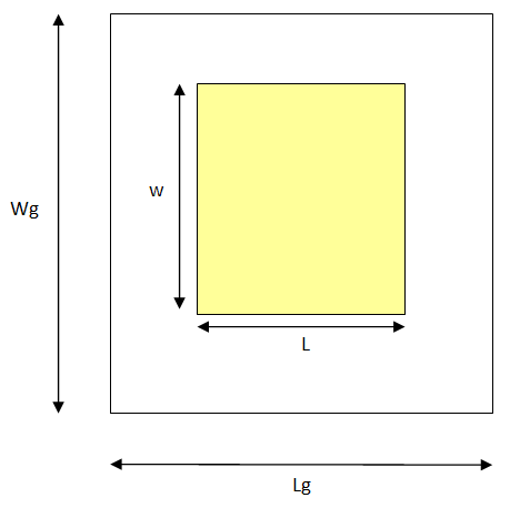
Wg: Height of the ground plane
W: Height of the path
L: Width of the patch
Lg: Width of the grounp plane
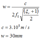
The following step will be the derivation of other dimensions using the characteristic of the antenna
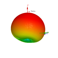
Microstrip Antenna design with Ansys HFSS
Height of a dielectric constant
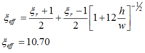
Effective dielectric constant ξef
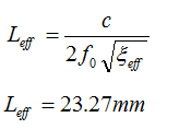
Effective length
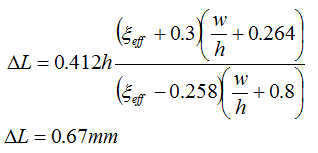
Length extension
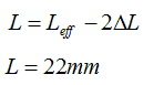
Actual length of the path
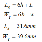
Ground plane dimensions
Now that we have all dimensions of the antenna, We need to design a transmission line to feed the antenna.
Design of the Microstrip Transmission line
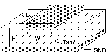
I will suggest you have a look at Bahl and Trivedi book titled ” A designer guide to Microstrip line” microwaves, May 1977, pp 174-182, here is an extract. (hope the link is still not dead 😉 )
The characteristic impedance Zo is a function of the ratio W/H and
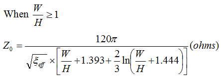
Since the value of the Zo is proportional to the W/H, we can alternatively change W and H and keep the value of Zo more or less constant. This is made for the sake of finding a value that will allow the transmission line to match our others dimensions. (remember the antenna + transmission line have to fit on the ground plane)
Using the following table, we observe that we have a choice between several W and H while keeping the Zo almost constant.
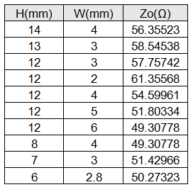
My concern here was to reduce the height as much as possible to help the whole (transmission line + radiating element) fit nicely on the ground plane.
We will then choose the last value for the antenna design: H=6 mm, W=2.8 mm
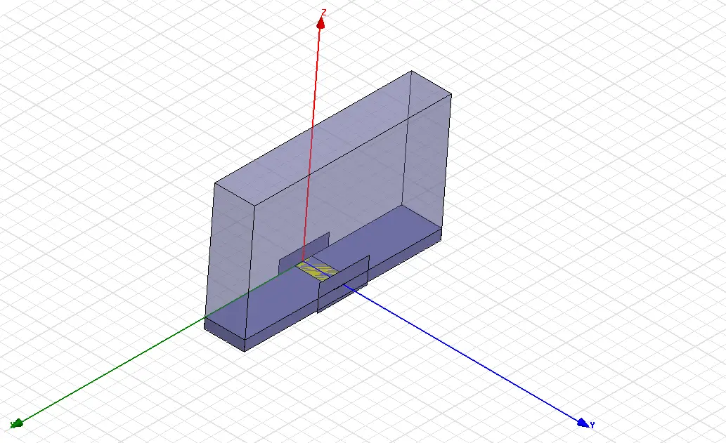
We now need to simulate the microstrip transmission line and make sure the return loss is OK. (under -10dB)
Just design the model as shown on the figure below, and have two ports set to 50 ohms with the transmission line in between those ports. Simulate it, and plot the S11 plot.
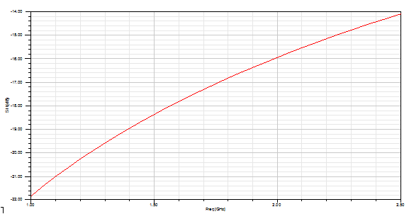
The plot above shows a return loss way under -15 dB for our chosen dimensions which confirms the design of a 50 ohms microstrip transmission line.
If you have trouble designing the transmission line in HFSS, you may need to have a look at this HFSS antenna design post.
Now it is time to join the antenna to its transmission line and simulate the whole in order to verify how both react when combined.
In part 2 of this post we will investigate the whole antenna simulation using the foundation laid down in this post.
Reference: A. F. Peterson: Microstrip transmission lines