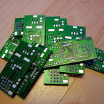
The industry of Computer Aided Design (CAD) includes Printed Circuit Board (PCB) design. Most people that are around technology have most likely seen a PCB. However, they probably were unaware of what it actually was. In simple terms, a PCB is a physical board with electrical components which performs one or many electronic-based activities.
I will share my expertise in PCB schematic and board design through the use of the Eagle PCB tool. This Eagle PCB tutorial will show a beginner how to take a circuit design (on paper or breadboard) to a PCB layout so it can be manufactured.
What Tutorials are Available?
There will be four categories of tutorials available. Tutorials will be consistently added to each category. To be notified of new tutorials, be sure to subscribe below.

The categories are:
- Basics of PCB softwares
- New Part Design
- Schematic Design
- Layout Design
Be sure to check out the list of topics you will learn, which software will be used and why, and how the tutorials are organized.
Tutorials for Basics of PCB Softwares
[ws_table id=”8″]
Tutorials for Creating a NEW Part in the Eagle Library
[ws_table id=”11″]
Tutorials for CAD Schematic Design
[ws_table id=”9″]
Tutorials for PCB Layout Design
[ws_table id=”10″]
Which PCB Software will the Tutorials use?
I chose Eagle PCB because it is widely used by the beginner (DIY) community and has a number of pre-made component libraries, e.g. resistors, integrated circuits, among others, available. However, you can use any PCB software and the same principles will apply.
In these tutorials, I plan to guide you in creating a full-pledged PCB, which you can apply in your projects.
What will I Learn?
In the entire series of tutorials, you will learn how to:
- Setup of PCB software to create projects, schematics, add libraries, among others
- Definitions of important options and menus
- How to add components and make electrical connections
- How to label and add text for clarity
- How to check if your design meets fabricator requirements, i.e. Electrical Rule Check.
- How to layout your electrical components efficiently on your PCB
- How to determine routing widths, use multiple layers and vias
- Tips and tricks on how to create an effective schematic
- Tips and tricks on choosing the right components, e.g. resistor sizes
- How and where to manufacture your PCB after completion
- And much more!
How are the Tutorials Organized?
 In general, each tutorial will consist of:
- Explanations of the tasks and their importance in PCB design
- Images and explanations of the steps
- Video tutorial
I encourage you to follow along with the video and/or images so you can learn while practicing. Eagle PCB can be downloaded here for Mac OS or Windows.
About Me
My name is Mushfiq. I have a bachelors (BSc) degree in Electrical Engineering and currently pursuing a PhD. I have created numerous PCB designs over the years and have 6 years of experience in this field. My projects have won several national and local awards for best design and innovative ideas. My goal is to share my knowledge with everyone because electronics are fun and useful.
Leave a Reply