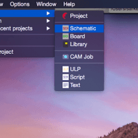
In order to send a PCB for fabrication, the first step is to create a schematic. A schematic is visual representation of the electrical connections. In the previous tutorial, I explained how to create a new project and schematic file so check that out before continuing here. First, it is important to understand the numerous options and menus available at your arsenal in the Eagle PCB software.
There are two toolbars in the software: top and left. I will explain these two toolbars in detail first. Then, I will explain the menus.
Top toolbar in Eagle PCB Schematics
In general, the top toolbar hold options related to saving, creating, and opening schematics. In addition, it also has options for zooming in and out, and zoom to fit to screen.


The highlighted red box on the left shows the open, save, and print options for your schematic. The right box shows the zoom to fit, in/out, and selected zoom. This is fairly straightforward.
Left Toolbar in Eagle PCB
This toolbar has a multitude of options that require explanation. Overall, this toolbar has the important options when creating your schematic. It allows you to add a part, add a electrical net connection, and more. Before continuing, make sure you understand the definitions and acronyms in PCB design.
Listed below are the most important options in Eagle software. As you continue through these PCB tutorials, we will use these options extensively.

- Move, Copy, and Rotate (red box)
- Move a object around the schematic window
- Copy an object, e.g. resistor, in order to paste it
- Rotate an object by 90 degrees
- Paste, delete, and add a part (green box)
- If you copied an object, then you can paste it using this command
- Cick the delete box then click the object you want deleted
- Adding a part option allows you to add components, e.g. ICs, resistors.
- Name and value options (blue box)
- Change the name of the component for clarity
- Change the value of the component
- Draw a wire connection, place a junction and label (orange)
- Draw a wire between two components to make an electrical connection
- Place a junction between two connections
- Place the name of the component as a label
- Electrical Rule Check (ERC) and see errors/warnings (black)
- Run the ERC to see if your schematic was created properly
- Show errors/warnings from the ERC tool
Menus in Eagle PCB
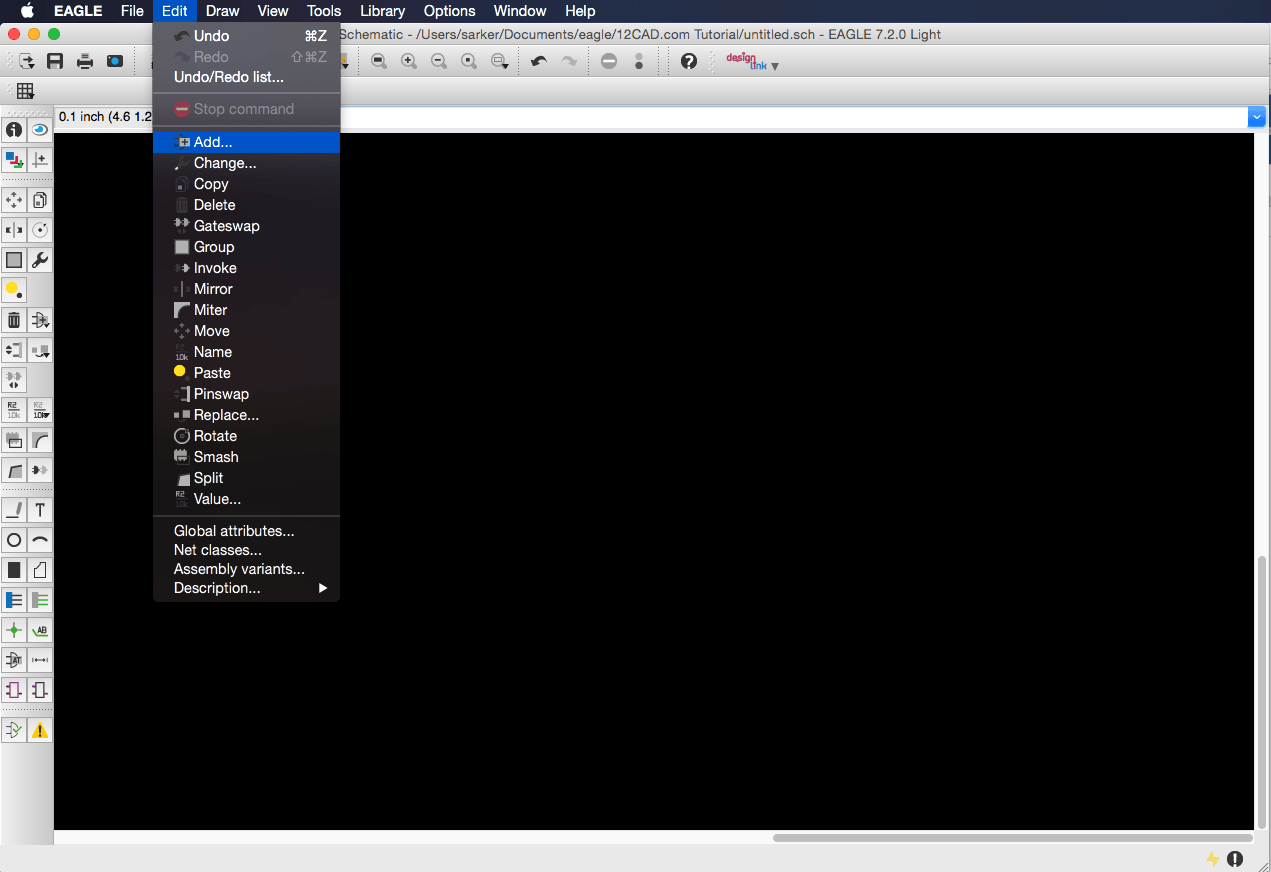
Similar to any software, menus are important. We will start off with the Edit menu as shown in Figure 2. We can see that most of the options covered above in the left toolbar are present here as well.
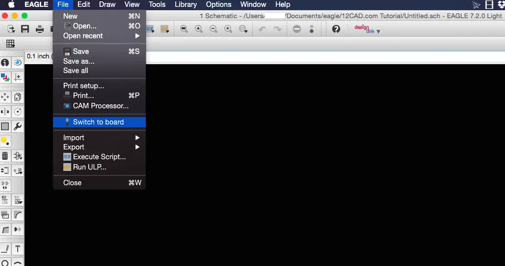
The next important menu is the File menu. All the options here are fairly straightforward. I want to specifically discuss the ‘switch to board‘ option. Once you have created a schematic, you can create a board layout. Eagle software will take each of your components’ footprint (e.g. resistor would have a 0402 footprint) and place them into a board file. Then, you are able to route your board which the PCB CAD fabricator will follow. Note that I will go into much more detail with this in a future tuturial. Stay tuned!
Video Tutorial on Menus and Toolbars in Eagle
Final Thoughts
In this tutorial, I covered the toolbars and menu options available in the Eagle CAD software. The best way to learn these aspects is to try it yourself. If you watch the video, you can follow along and learn while practicing. You can also refer to the user manual available by CADSoft.
Do you have any questions/concerns? Leave a message below in the comments.
Comments
One response to “Schematic Options and Menus in Eagle PCB – Tutorial”
[…] schematic window should look similar to Figure 2 below. I added the parts and rearranged them by moving and rotating them. Now, we can start adding the electrical connections […]