This article will be of interest for those who want to obtain the first certification from SolidWorks which will involve 3D modeling, drawing comprehension and assemblies. This is the first certification you must obtain in order to proceed with any further SolidWorks official certification that are listed in their website.
The following exercise will be a model exercise and the drawing can be downloaded directly from BS SolidWorks website and clicking “sample CSWA exam”, it is highly suggested to read all the information if you are truly interested in achieving this certification: http://www.solidworks.com/sw/support/796_ENU_HTML.htm
Also, make sure to check out our detailed Solidworks tutorials here.

CSWA Certificate Example Exercise #1
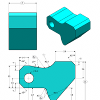
All of SW sample tests questions will resemble the certification test questions. Therefore it is truly suggested that a practice/exercise test must be made. We will walk you through this first exercise where the following is being asked:
Unit system:
MMGS (millimeter, gram, second) Decimal places: 2
Part origin: Arbitrary
All holes through all unless shown otherwise. Material: AISI 1020 Steel
Density = 0.0079 g/mm^3
A = 81.00
B = 57.00
C = 43.00
What is the overall mass of the part (grams)?
- a) 1028.33
- b) 118.93
- c) 577.64
- d) 939.54
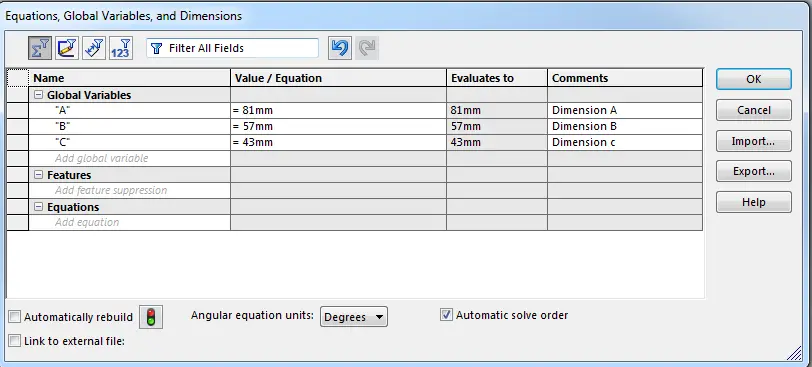
Equations:
Let’s get started by building an equation to introduce the values of A, B and C. This will allow to modify them more easily. The command for equation is the following:
Tools => Equations
Analysis sketch/planes:
Before rushing to start drawing, is it advisable to observe and take your time to analyze the abstract work piece per plane and plan the sketches which will be extruded and the ones that will be subtracted if needed. Don’t forget to check your units!
The drawing will be made in the front plane to resemble the isometric view that it is given in the drawing.
We start by making a rough sketch of the model; restrictions and dimensions will be added step by step. Observe that the sketch in the next image only has simple restrictions of coincident points and horizontal/vertical lines. The sketch has two circles where the centers would be located. The origin doesn’t need to be as shown in picture, it is free to choose by drawer.
Restrictions/relationships/constrains
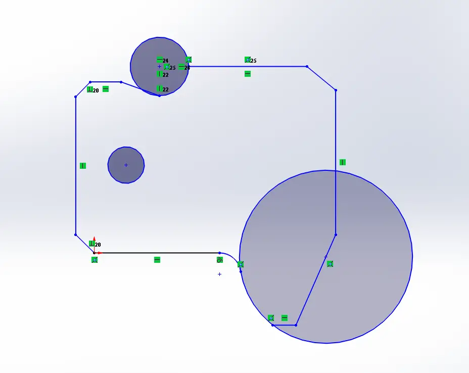
The next step is to start adding some restrictions to your sketch. This is very helpful for the next step in order not distort your sketch when you start adding some dimensions! The constraints and restrictions are highlighted in the next image. Notice they are mainly horizontal and vertical linear patterns that we added.
Dimensioning and Trimming:
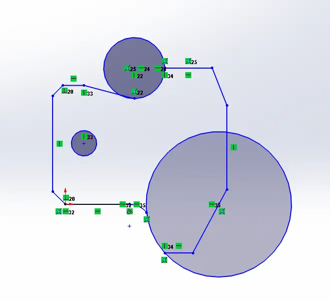
After adding some restrictions, it is time to start dimensioning our sketch. It is preferably always to draw according the dimensions given in drawing that way when you use “smart dimension” there will be even lower probabilities to distort the figure and finish your sketch quicker. Making the rough sketch will benefit you in dimensioning quicker. The next image shows the first dimensions given to the sketch, notice the lines turn black when it’s completely defined. All proper sketches must be completely defined, this will make it much easier when you decide to redesign or change dimensions.
One of the best tools for sketch is the trim entities tool, which will allow to cut lines or curves that coincide with others, allowing you to create figures and shapes according to your needs. In this case, we used the trim option to be able to create a radius from a center point.
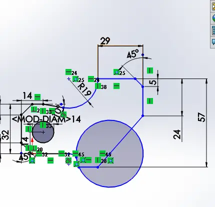
To add the equation dimension, use the option smart dimension and type the characters you named for the equation, in this case the dimension B will be added which was given in the description of the problem.
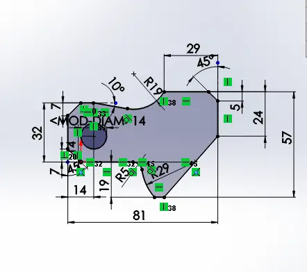
The next two pictures are all about adding the rest of the dimensions that the drawing shows you. This is still continued in a clockwise pattern to follow an order.

Dimensioning right side origin
After trimming the second circle, another restriction that must be added is the tangent relationship. This will allow us that a curve or a line will only touch the circumference or radius of a figure in one single point.
The sketch is almost finished at this point! Just a couple more dimensions to define and keep track of which dimension you already established in your sketch. Crossing those already used is a great tip for beginners.
Sketch finished!
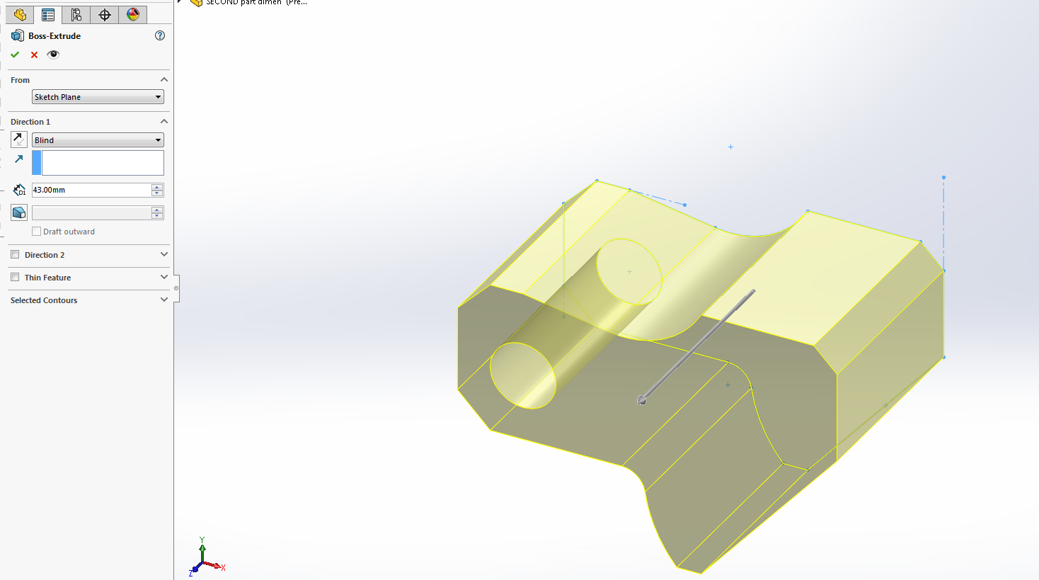
Extrusion
The last and final part is the extrusion, which will be given the value of dimension “C” from our equation list.
Answer the Question: What is the overall mass of the part (grams)?
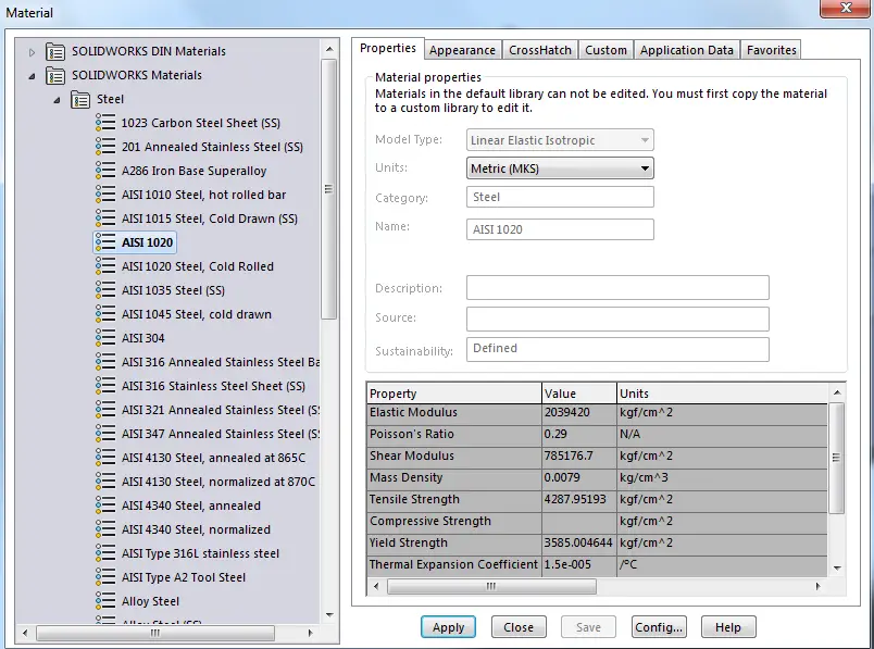
When you draw and extrude a solid mass, the work piece will be predetermined without a specific material. Therefore you need to right click on your part in the operations menu. Then select Material=è Edit material
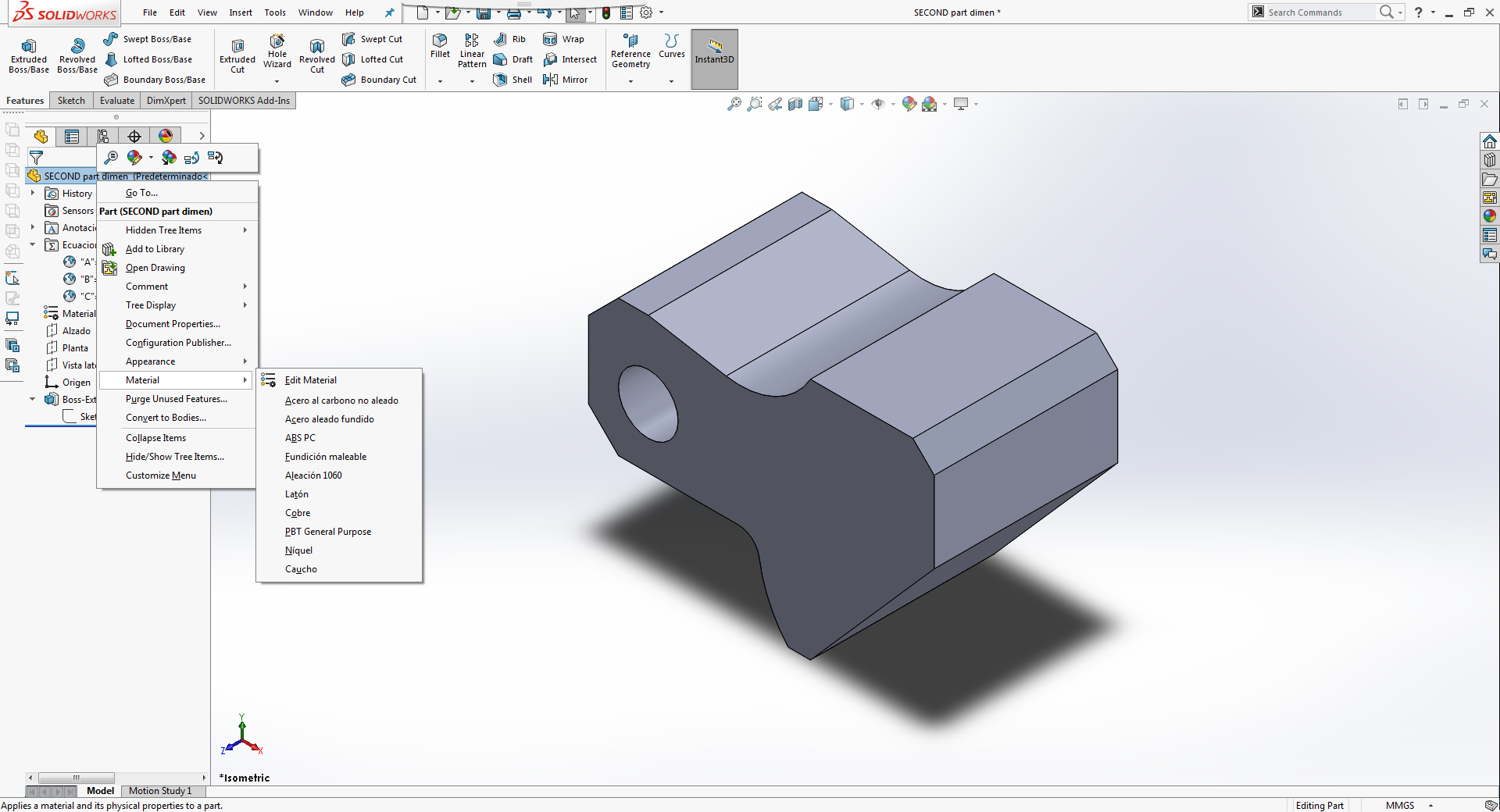
A list of materials will appear with the option to choose whichever you need or plan to design with. In this case the problem requires you to add a steel AISI 1020.
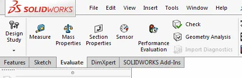
To check your results. It is need to click in EVALUATE => Mass Properties.
Verifying results:
By clicking in mass properties a window will pop up, showing a lot of information such as density, volume, mass, center of mass, moments of inertia and so forth. In this step we much conclude that the overall mass of the work piece is:
a) 1028.33
b) 118.93
c) 577.64
d) 939.54 (Correct Answer)
Conclusions:
It is highly important to practice sketching and interpreting abstract drawings in order to certificate in this first SW exam. This is only an example of the steps and procedures one must do when attempting to make a sketch which will, later on, need to be verified with mass or other values shown in the mass properties option. A single dimension mistake or missed will lead you to a considerable change in these values, therefore practicing and knowing sketch operations and restrictions will give you the tools needed to define your sketch and being able to obtain the right value asked for which must be in the multiple choice options in the exam.