
This post shows you how to draw a Pulley in CATIA using Boolean operations.
There are many reason you as a beginner should master how to use Boolean operation in CATIA. It is one of the preferred method used by CAD designers for the following reasons.
- It is easy to model a part using this method.
- Editing the model without failure is possible.
- One can easily get idea, how the core will look like in case of plastic or casting components.
Let see how this works.

We will be designing a Drive pulley using Boolean operations.
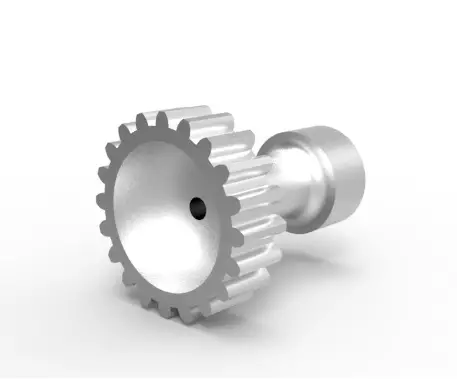
Here are some dimensions of the pulley.
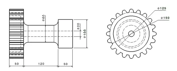
One can easily understand that there are three major parts in this component.
- Input gear
- Shaft
- Pulley
Our strategy will be to make these three individual parts separately so to be able to join all at the end of the design.
Step 1
In the specification tree, I have added 6 bodies and renamed them to a suitable name.
In these bodies we will create features.
Step 2
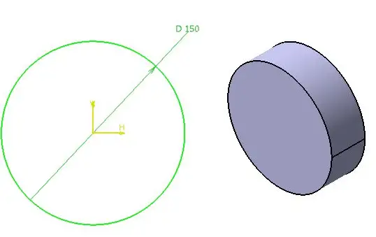
- Right click on Power Input Gear and Define it. In this body we will create gear.
- On the front plane draw a circle of 150mm diameter.
- Extrude it to 50mm distance.
On the same plane draw gear tooth profile.
Using circular pattern complete the gear.
Step 3
- To create the core of the gear, define next body as in work object. Create a plane at a distance of 10 mm from front plane using Plane option. (You will find Plane option in the Reference Elements toolbar.)
- Draw a circle of diameter 125mm on this plane.
- Extrude it to 40mm.
Step 5
- Now we will create the shaft. Define shaft body as in work object.
- On the front plane draw a circle of 60mm and extrude it to 120mm on the opposite side of gear.
Step 6
Before creating shaft core we will create pulley. In pulley body, take a plane offset of front plane at a distance of 120mm.
On this plane draw a circle of 100mm dia. and extrude it to another 50mm.
Step 7
Now we will create shaft core. Activate Shaft Core body.
- On the front plane, draw a circle of 20mm diameter.
- Extrude it to 170mm distance on shaft side and 10mm on the gear side.
We will get a core, with total length of 180mm.
Step 8
After creating all the basic parts, we will perform Boolean operations.
At the very first step we have created a body named as Drive pulley – Main Part. We will Add and Remove features in this body to get our final component.
So which body do we have to add or remove?
It’s easy. The body which was named as ‘Core’ has to be removed from Main Part and all other bodies are to be added to the Main Part.
At the end, click on Drive pulley – Main Part and define it in work object. Give appropriate edge fillets at sharp edges and you should have the final component looking like the following.