In terms of assemblies, and this methodology of design, multiple sub-assemblies can exist in a main assembly, hence advocating a parent child relationship among the assemblies. In sub-assemblies, we have a combination of elements that make up the sub-assembly, some parts restricted or locked in place, others free for manipulation.
In order to exercise that manipulation, the norm would be to access the sub-assembly and then operate it’s mechanics in whatever manner is desired. This is logistically maintainable, because you will probably wrap everything up in one sub-assembly before moving to another. Also, it singles out the entity which can prove crucial when reviewing the design work of another engineer or handling large-scale projects with hundreds of sub-assemblies.
But time and again, experience has given way to the need of a bird’s eye view of the entire project and the subsequent need to manipulate parts within different assemblies concurrently. Furthermore, when testing the final revisions a complete view of the system is a must have. For this purpose, and/or others as Dassault Systems’ discretion, the rigid and flexible properties exist. In this tutorial, we will teach you how to use rigid and flexible assemblies in SolidWorks. Check it out!

What is a Rigid and Flexible Assembly?
Let’s dive straight into the matter of what is a rigid or flexible assembly. In classic fashion, a rigid assembly is a rigid body, the way it’s described in physics. It does not allow transformation, manipulation or other movements of any sorts. The exact opposite is the flexible assembly. This assembly, if it has any movable (or controllable) parts within it, will allow the direct manipulation of those parts without having to access the sub-assembly each time.
A Quick Look
| Rigid | Flexible | |
| Movable from within sub-assembly | Doesn’t apply* | Doesn’t apply* |
| Movable from within parent assembly | No | Yes |
| * Rigid/flexible properties do not apply to manipulations from within the sub-assembly because any free part will be allowed to move by default (as it in “edit” mode) | ||
Now before we see how these properties are applied and what that does for us, let’s talk about one more thing. And that’s basically targeting the issue of universal flexibility. In terms of assemblies, two kinds of assemblies exist. One is the fully-resolved kind and the other is a lightweight assembly. Just for clarification, lightweight assemblies cannot be solved or resolved as flexible. This is because a lightweight is an assembly which is loaded with its most basic/required parts loaded into the memory. Any part/element/entity/property not required is not loaded completely. This is to make optimum use of system resources.
This optimized use of the resources is the reason why flexibility is disabled by default. A fully-resolved assembly is one which when loaded has all components loaded and ready for manipulation no matter what the requirement of the moment. Only fully resolved assemblies are made to be flexible otherwise a lightweight assembly may probably crash once editions are committed and then the unloaded parts are loaded.
| Fully resolved | Lightweight | |
| Movable from within sub-assembly | Yes | Yes |
| Movable from within parent assembly | Yes, if flexible | No |
Tutorial of Rigid and Flexible Assemblies in SolidWorks
Note: you can click on the images to get increase resolution and clarity.
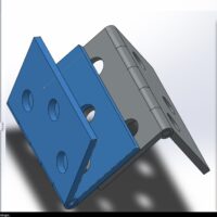
Now, we go ahead and see what we can do with the flexible and rigid option. Since the following text contains instructions, please notes that the SolidWorks version 2012 was used in addition to “Hinge Joint by Shubham Dharviya” available for free here. The below screen shows two hinge joints highlighting one of the selected hinges out of the two.
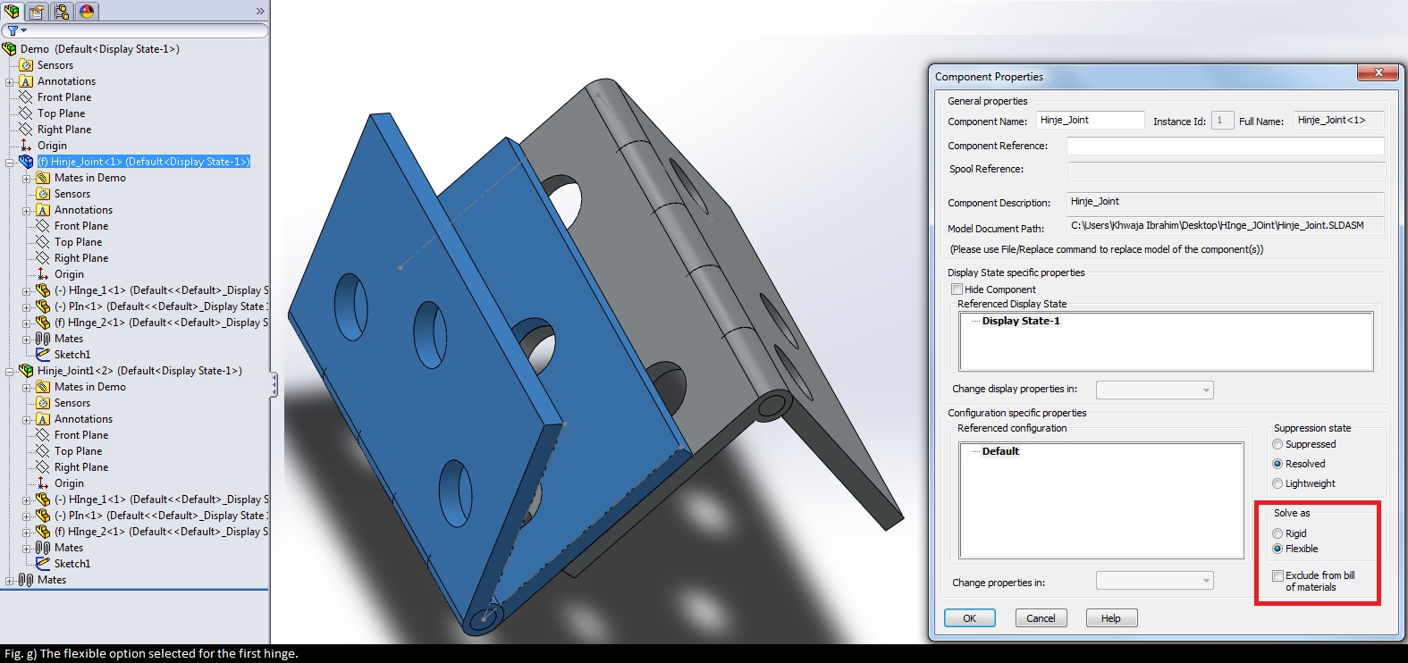
Right click on any one of the sub-assemblies to see its property.
As of now the model I have is flexible, hence the hinge is movable.
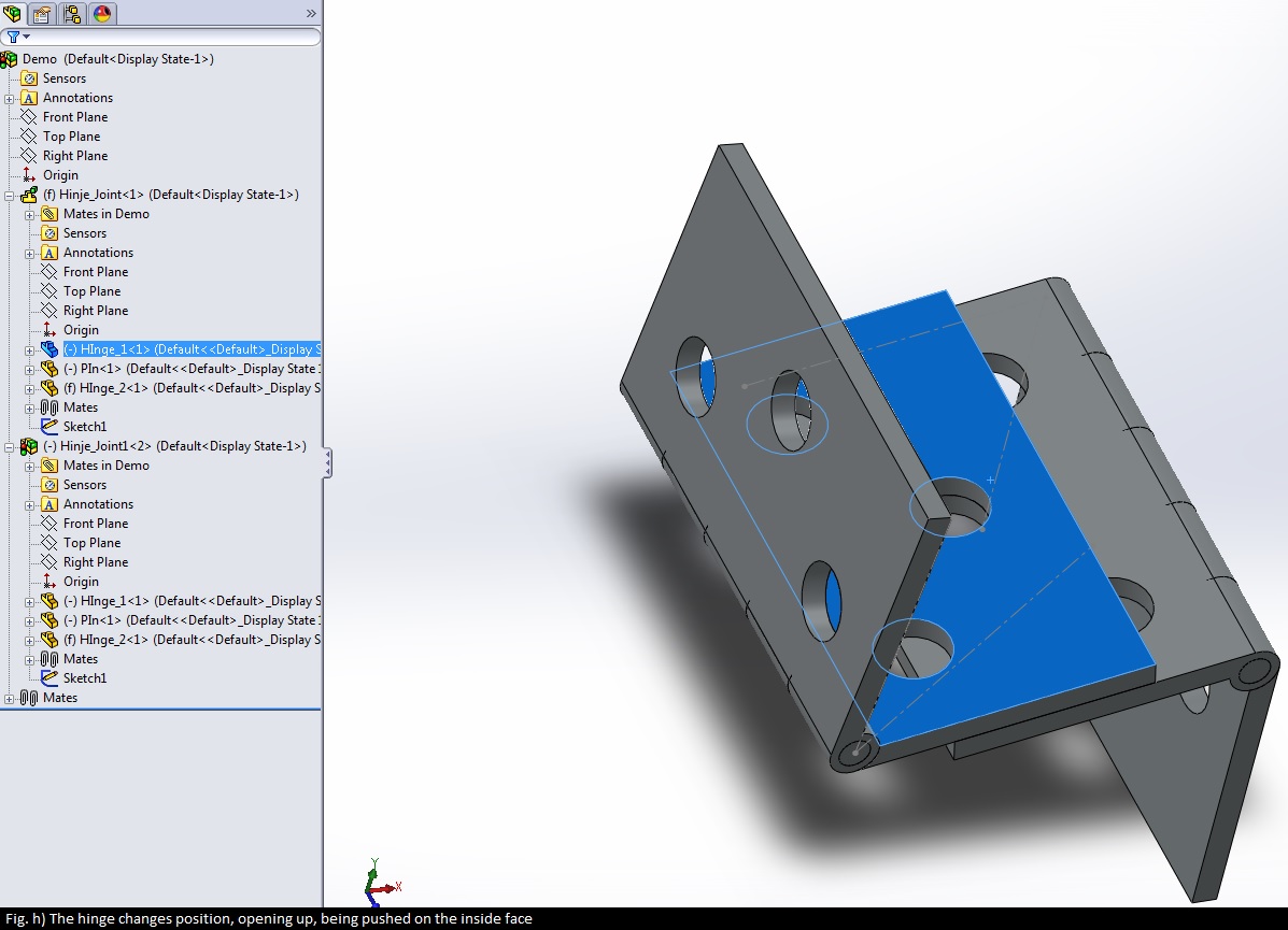
The movement of the hinge can be noted by the selection of the inner face of the hinge (having turned blue). Using mates, the other hinge is held together in place and moves along with the movement of the first. Now let’s edit one of the plates.
In Fig. d, we can see the edit canvas for the hinge. We are now in the sub-assembly with the part in the same position that it had in its rigid version when working from the main assembly. This is because all free parts and their movements need to be calculated every time hence when the rigid option is selected, it reverts it back to its default/pre-calculated position.
With the face pushed up, we save the changes and go back to the main assembly view.
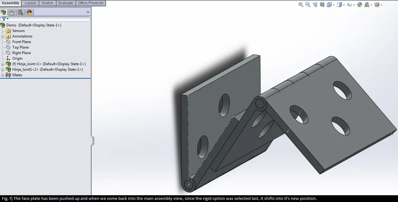
The main assembly view has the hinge shifted to its new position. Next, the flexible option:
Let’s see the hinge change posture with the flexible option selected (see Fig. h).
With all that said and done, the rigid and flexible options are literally, all covered. Furthermore, there are mates that always need to be focused on. See below.
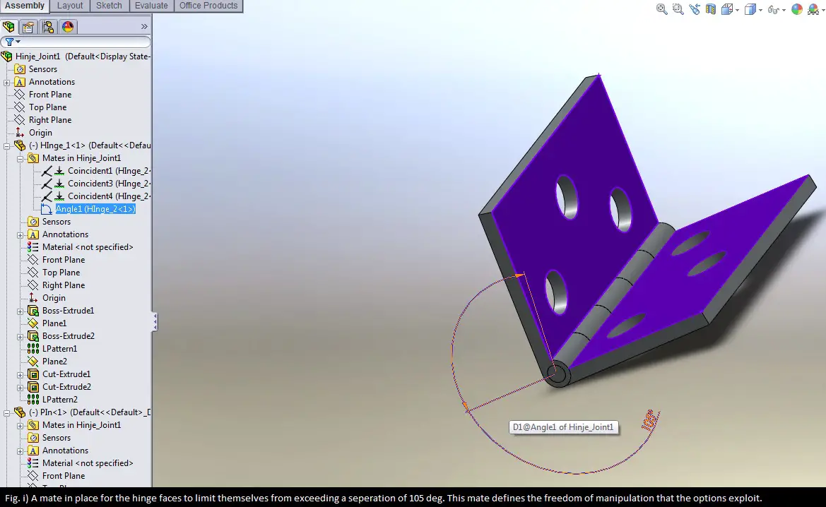
Mates give the elements the bounds with in which they can be manipulated. Hence, these mates allow the designer to align or control, centralize or justify objects and lock them in place for the combination to stay intact and to make it react while another sub-assembly is being controlled/manipulated (while constrained by a mutual mate).
Wrap Up
And that’s all there is to it.In summary, we went over how to use rigid and flexible assemblies in Solidworks. Also, fully-resolved and lightweight assemblies should not give you any problems now as well since that was covered.. If you have questions or something related that you think may help please post as a comment below. And as always, don’t forget to practice this on your own and try our other tutorials.