In this session, we are modeling an Alloy Wheel in CATIA using simple techniques.
An alloy wheel is a substitute of commonly used steel wheels. It integrates all parts of a normal wheel: wiz. Rim, Spokes, Wheel Hub…
Alloy wheels are generally lightweight than common wheels, thus they improve vehicle performance.

Modeling an Alloy Wheel in CATIA
Step 1
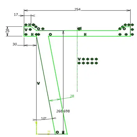
Draw a cross section profile for the rim as shown below. This profile features standard dimensions.
Using simple sketcher commands like Line, Mirror, Trim. you can get following sketch.
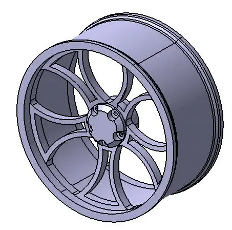
Using Shaft command, revolve the sketch.
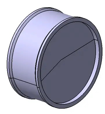
Step 2
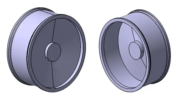
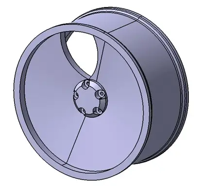
We now have the overall body of the wheel.
To mount the wheel on the axle, a wheel hub is necessary. The wheel is bolted to the axle.
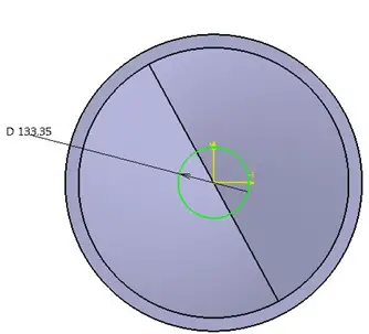
Draw a circle on the plane taken at the center of cross section profile. Extrude this circle up to 90 mm distance.
Step 3
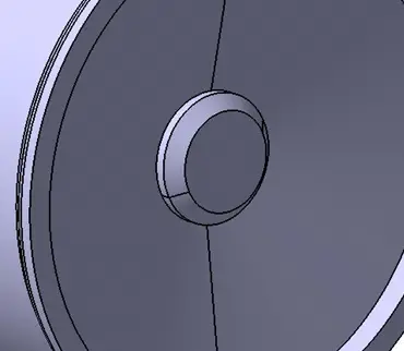
Give Chamfer to the front end of the hub as shown on the image below.
Step 4
Now to bolt the hub with axle we need holes in the hub. We will create 5 counter bored holes.
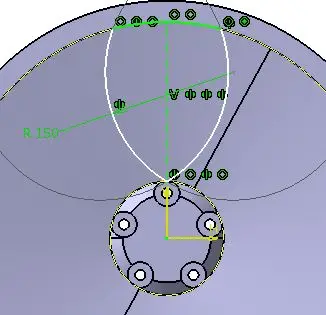
Make a hole using hole command and Positioning Sketch, on Pitch Circle Diameter (PCD) of 55mm.
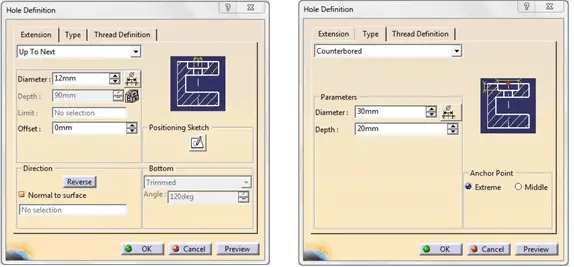
Do not forget to select the Counterbored Hole as hole type and you can use dimensions I have used here.
See the preview of the hole and if it looks appropriate, click OK.
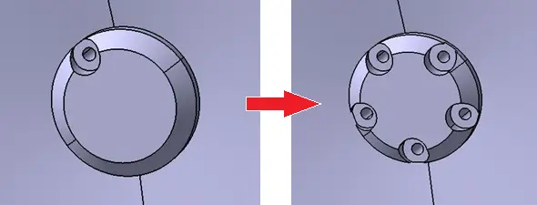
Use complete crown of these holes for creating Circular Pattern. Make 5 such holes in the pattern as shown.
Step 5
Our wheel hub is ready.
Now we will create spokes.
These are not actual spokes in case of alloy wheels, but the terminology hasn’t changed over the time.
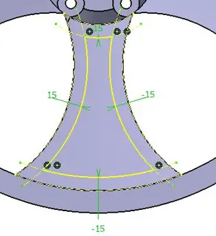
Draw a profile on the front plane as shown.
Using Pocket command, remove the material from the base object.
Using Circular Pattern to create a pattern of 5 pockets. (follow the same technique as in step 4)
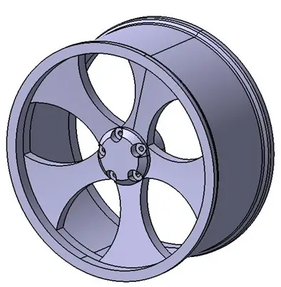
Now draw another profile as shown and remove the material.
Again using Circular Pattern, complete the Spokes.
You can draw this profile with the Offset command in Sketcher.
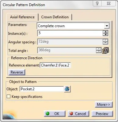
While using Circular Pattern, if you do not get the axis as Reference element, then you can click any circular shape in the model and it will automatically take axis of that element.
Now the alloy wheel is almost ready.
You need to use the FILLET command on edges wherever necessary to make the model look “cooler”.