Tag: how to use Eagle PCB

How to Draw an Electrical Connection in a PCB Schematic
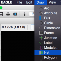
Now that you know how to add parts into your schematic, you are ready to learn the process of connecting these parts electrically. In Eagle, this is known as nets. Similar to the process in real-life (e.g. breadboard) where you make make electrical connections between parts, Nets allows Eagle to understand how the circuit is built. It is a…
Schematic Options and Menus in Eagle PCB – Tutorial
In order to send a PCB for fabrication, the first step is to create a schematic. A schematic is visual representation of the electrical connections. In the previous tutorial, I explained how to create a new project and schematic file so check that out before continuing here. First, it is important to understand the numerous…