Linear stress analysis with SOLIDWORKS Simulation enables designers and engineers to quickly and efficiently validate quality, performance, and safety—all while creating their design. In order to carry out stress analysis, component material data must be known. The standard SOLIDWORKS CAD material database is pre-populated with materials that can be used by SOLIDWORKS Simulation, and the database is easily customizable to include your particular material requirements.
Before proceeding, check in your system that the SolidWork’s complement for Simulation has been correctly installed. Also, make sure to check out our other detailed Solidworks tutorials here.
Step-by-Step Tutorial Stress and Failure Analysis
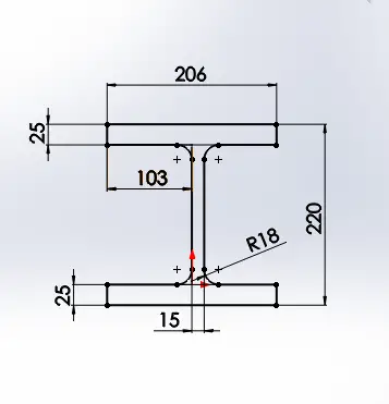
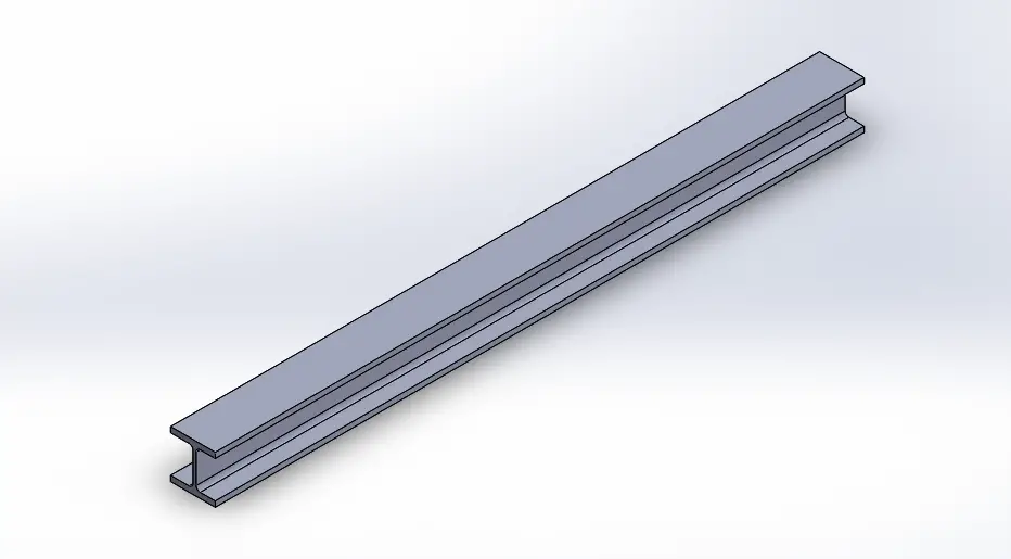
For this stress analysis explanation, a beam will be drawn from sketch. The dimensions of a standard beam can be found easily in the web. In this case, a beam was chosen from the category HEM which means that they are designed for reinforcing or building structures. The profile beam dimension is 220mm and the rest of the dimensions can be obtained in the following link.

Assigning Material to Work Piece
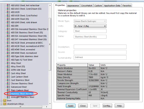
The next crucial step in order to make a correct failure or stress analysis, is to add a material to your design. SolidWorks have a general list of materials divided into different categories such as: steels, irons, aluminums, wood, plastics and so forth. Searching for the right material and correct yielding properties will allow you to make a more realistic simulation of your design.
For this purpose, a general stainless steel material was assigned to the beam. For specific cases, you can add your own custom material following the next steps:
- In a part document, right-click Material in the FeatureManager design tree and select Edit Material.
- In the material tree, select the material on which to base the custom material.
- Right-click and select Copy or press Ctrl + C to copy the material to your paste buffer.
- In the material tree, select a category in a custom library. You can use the Custom Materials library or a library you created.
You can only add custom materials to categories within the Custom Materials library, not to the Custom Materials folder itself. To create a new category, right-click Custom Materials and click New Category.
- Right-click and select Paste or press Ctrl + V.
- Optionally, rename the material. Right-click the material and select Rename.
- Edit properties of the material, then click save.
- Optionally, click Apply to apply the new material to the current part.
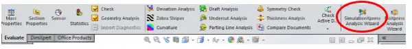
Once a material has been applied to the work piece, choose the option “SimulationXpress Analysis Wizard” located in the evaluate window to start the analysis.
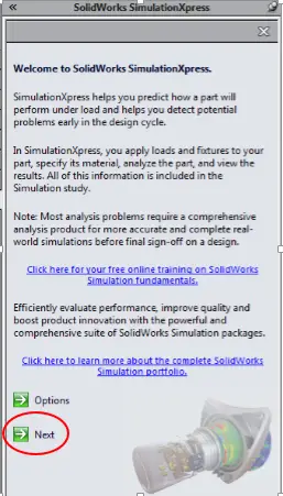
The SolidWorks SimulationXpress Analysis will start with a brief explanation screen of the advantages or the purposes you can use with this complement of SW. Hit the next option to continue.
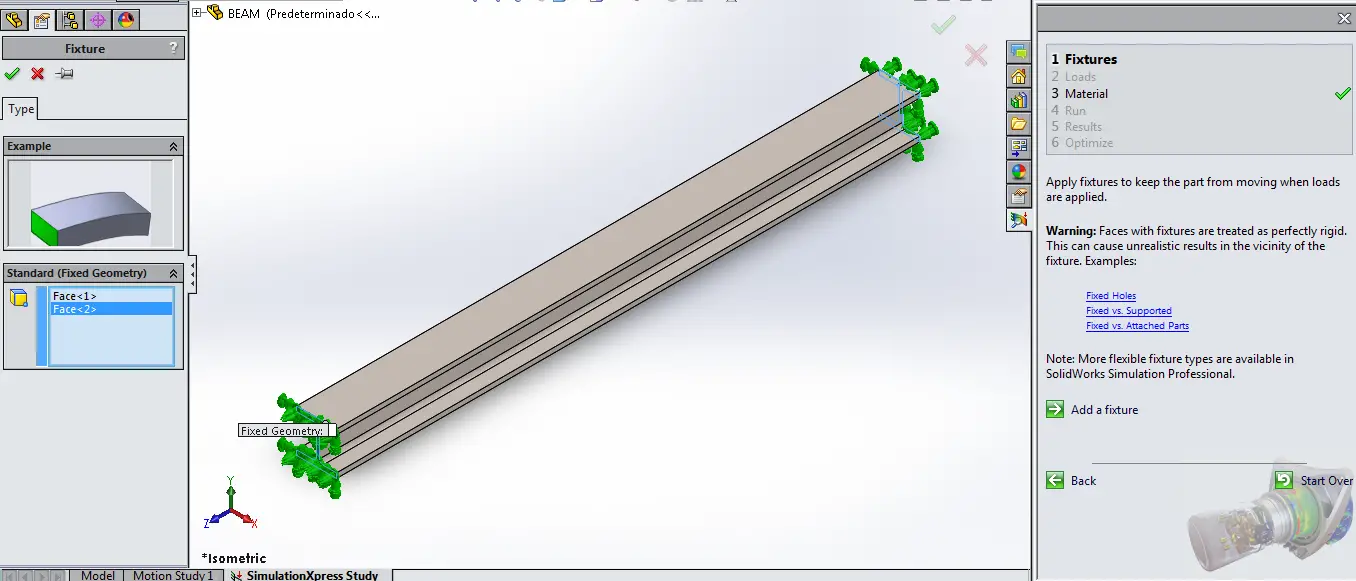
Adding Fixtures for Simulation
The next screen that will be shown is the fixtures options. Fixtures will allow you to simulate a fixed geometry in the work piece’s faces or edges. A fixture must be added because when a force is applied, there must be an area of contact in which the work piece must be fixed or static. Add all the necessary fixtures you may need to replicate a case where a load is applied to your design. The fixtures added in this beam are located in the H’s faces where it should be mechanically fixed in a real life application.
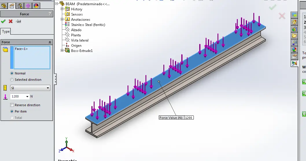
Applying a load to Work Piece
For this first example, we will add a force applied to the face of the beam as shown in the next picture, you can modify the direction of the force or change the units of it.
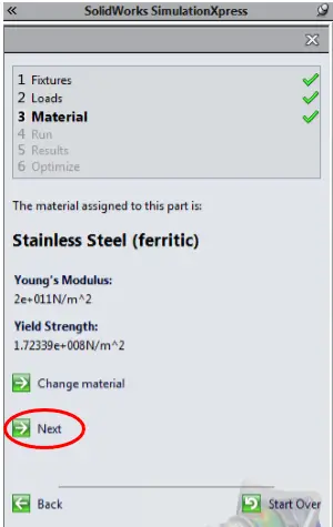
Checking Material Assigned
The next requested step which is already done, is to add a material to your work piece or design. If a material was already assigned before using the “SimulationXpress Analysis Wizard”, it should show you in the next screen as it shows in the following image.
Run the Simulation
The following screenshot, shows how SolidWorks interpret the force application according to the fixtures you have provided to the program.
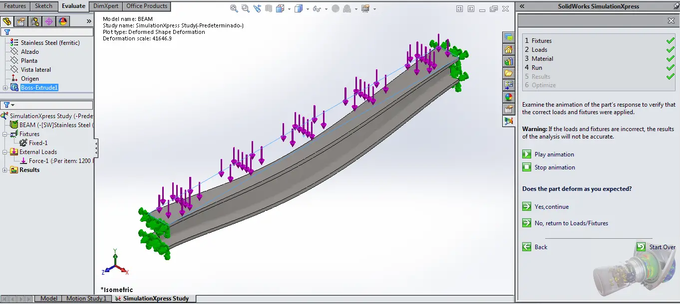
A SimulationXpress study tree will also show up in this step. Allowing you to easy modify the variables you have already assigned or filled up. Allow SW to complete all the simulation if you decide to make changes in the next steps. Click on the option “Yes, Continue” for SolidWorks to start the simulation. Depending on your simulation complexity and system speed this could vary on time.
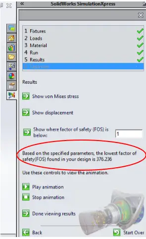
Factor of Safety
This final optimization step will allow you to modify an important factor which is the factor of safety (FOS). Every design especially if you are talking about a structural one, must have a factor of safety. The formula to calculate the factor of safety is the following:

Every work piece according to its material and design possess an ultimate stress value and nominal stress value. The factor of safety will relate both of them and give you a reliability value which will tell you if your design will efficiently work on the application or if it will prone to fail. SolidWorks automatically calculates an estimated FOS which in this example it’s pretty high therefore with the constant load applied of 1200N this says it’s really reliable for this test.
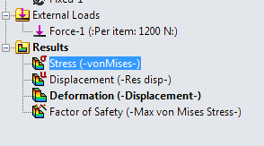
Stress and Deformation Analysis
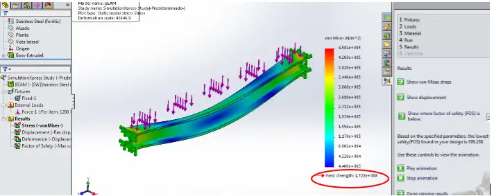
The following image shows for this example the Von Mises which will also indicate your material’s final yield strength. As it shows in the image the yield strength is much higher than the stress that recieves the workpiece in the fixture zone areas.
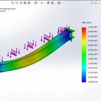
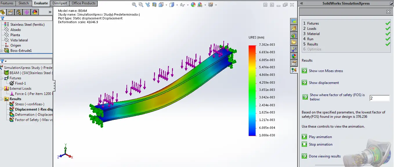
This other screenshot shows the deformation that the work piece could suffer. The most deformed zones are clearly the ones that aren’t fixed and that are more likely to bend due to current conditions.
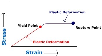
Nevertheless, the most affected zone hasn’t considerable deformation and it’s far away from plastic deformation. If we were to take out the load, the material would return to its original state before the slight deformation. This test is clearly still in the elastic region according to the next diagram behavior.
Creating a Report from SolidWorks
SolidWorks will ease the work even more by creating a report involving all the variables and information you have given up to now. The two options to report your results are the following: a Microsoft word report or e-drawings file to open. In the word report, you will basically find a summary of all the six steps you assigned values or managed which are: fixtures, loads, material, factor of security and mesh type for the simulation.
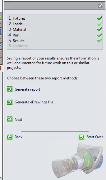
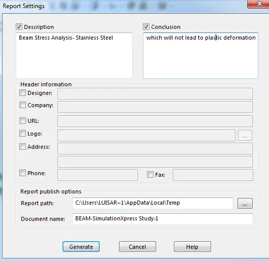
Finally for the report, you can save it and add some comments and information of the company or the designer who created the simulation. This will also be added in the report that will be shown according to the option you previously chose.
Conclusions
As shown in this example, SolidWork’s simulationXpress tools really provides a good simulation for design, optimizing and detail a work piece for a stress/failure analysis. These tools are totally customizable and user friendly for all engineers and designers who attempts to demonstrate a stress or failure analysis. The reports of SolidWorks will aid on the presentation of such results and simulation overview.