
Dimensioning is a general task for any drawing or drafting engineer. Every 3D model needs a 2D drawing to accompany it for manufacturing, hence the dimensioning needs to be annotated precisely. For larger or complex designs, this task can be very time consuming as well as redundant in light of the fact that SolidWorks has a feature that will do the work for you and with just a few clicks.
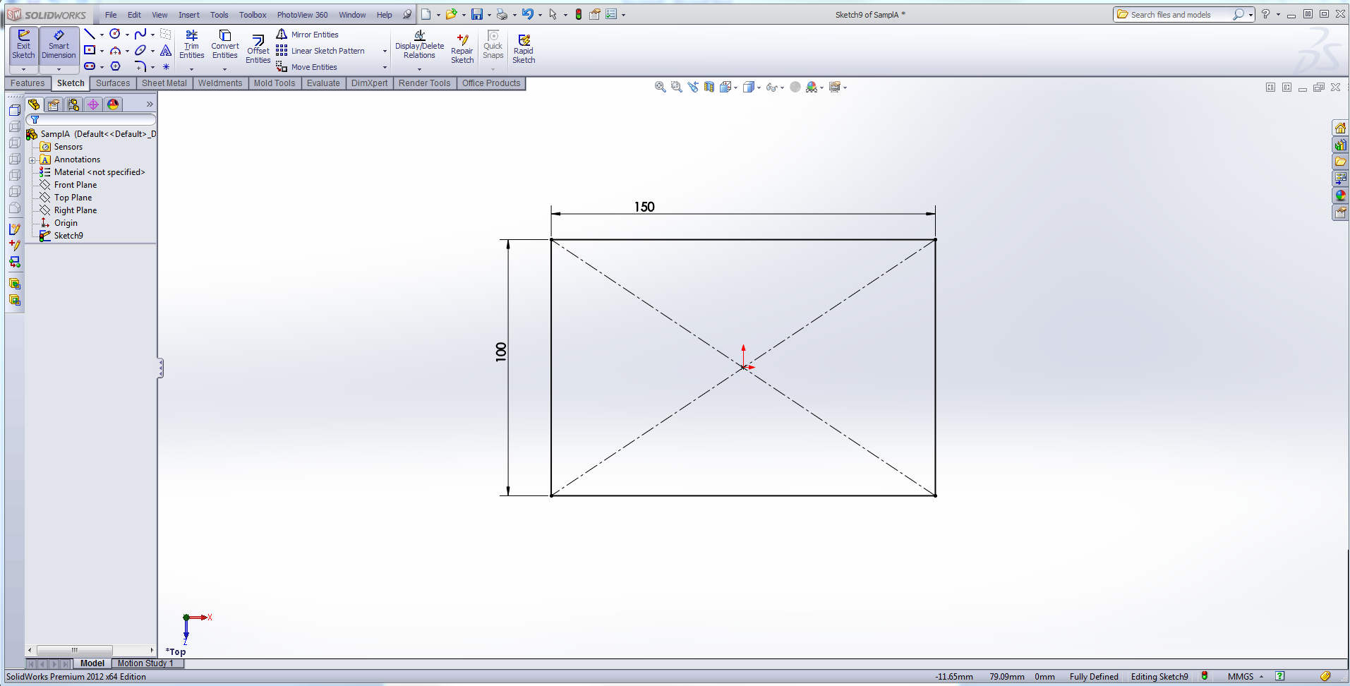
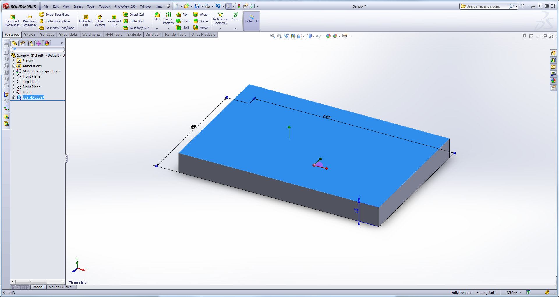
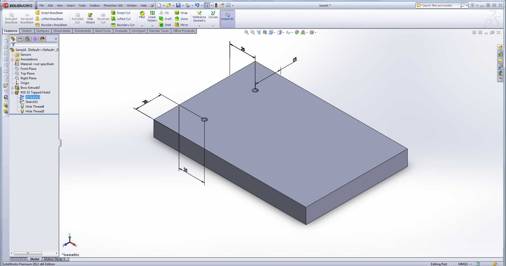
Before we move on to see the actual function and how to use it, let’s go through a small series of images showing the initial design (3D) phase. Take a look, so we can see the dimensioning which will get replicated later on:
Now from here on, we’re going to take the 3D drawing and generate a 2D drawing, which we will add the dimensioning to later. Check out the steps below:

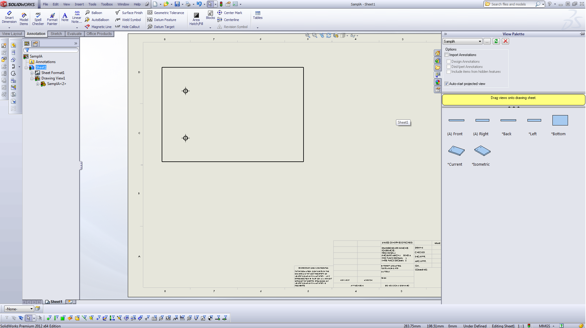
Using the “View Palette” we can add the views of the 3D design to the 2D drawing. Notice how the “Top” option is missing, since we have already added that to the drawing. For future notes and demonstration of extra options, I’m going to add another face here.
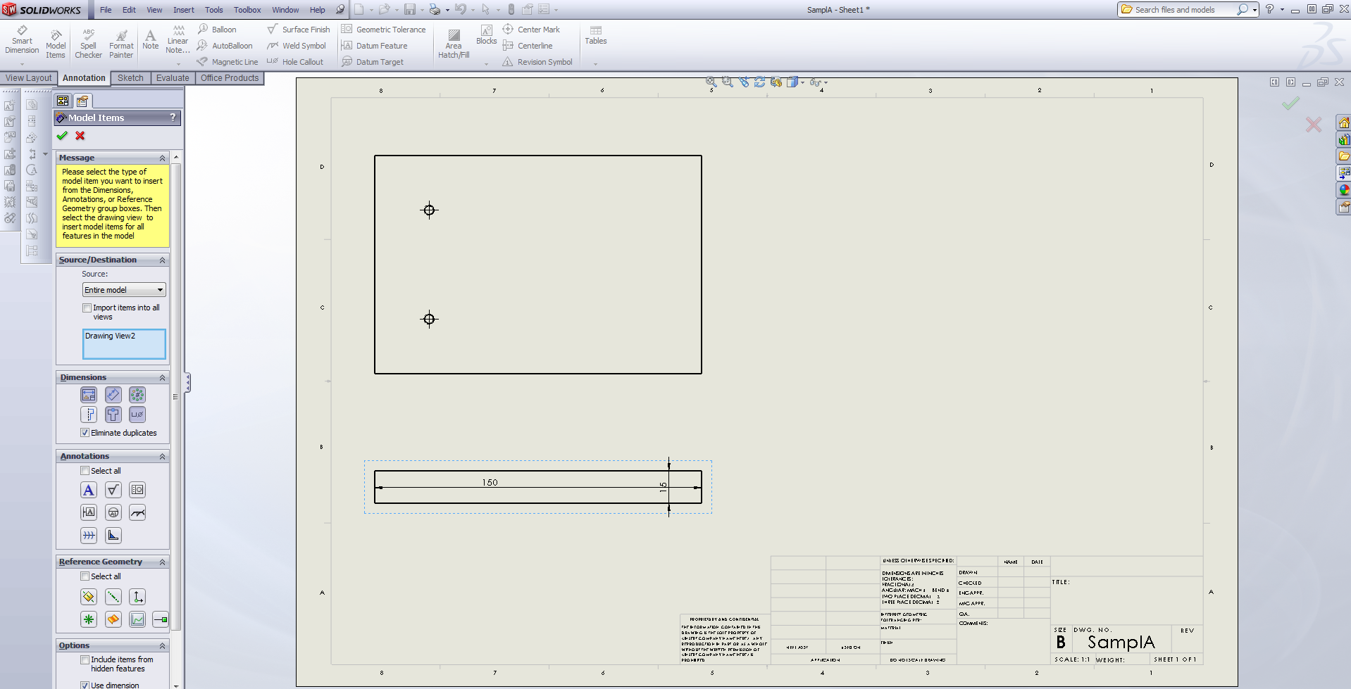
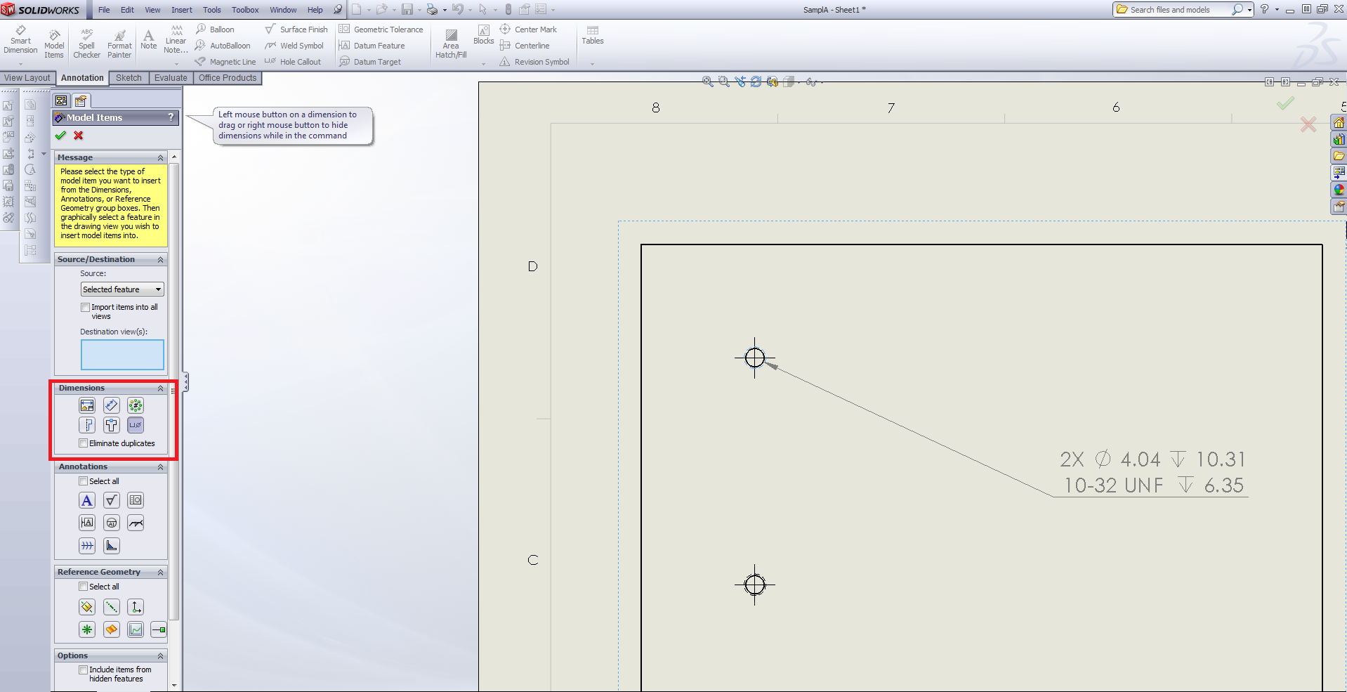
With the front view also added, I’m going to go ahead and use the “Model Items” option present under the annotation tab to label the features with dimensions. As can be seen below, the window allows you to select more than one option, which are “Entire model” and “Selected feature”.
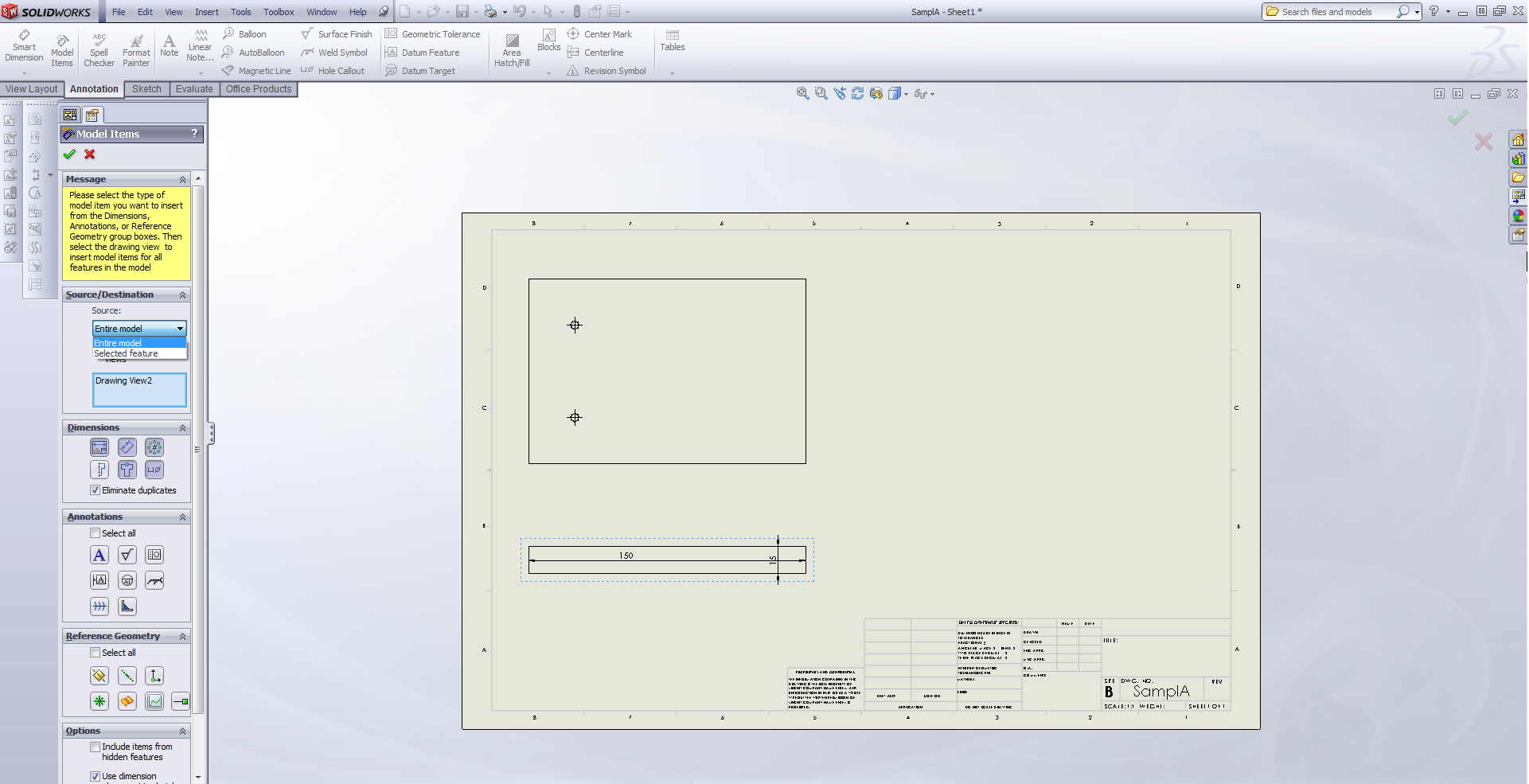
First we select the entire model for dimensioning and check out the rest of the options. The option right below, visible in the screenshot previous to this last one, is one that allows you to import the dimensioning functionality to all views on the sheet as opposed to just that of your choice. The buttons in the dimensions tab are already selected and those are miscellaneous options that we’ll see in a minute. Below that we have the annotations tab and so on. Now with the entire model selected for dimensioning on all views, let’s do what we came here to learn.
With only a single click of the encircled check mark (below) we now have dimensions showing by default. The way the dimensions show up is a matter of the options we selected under the dimensions tab.
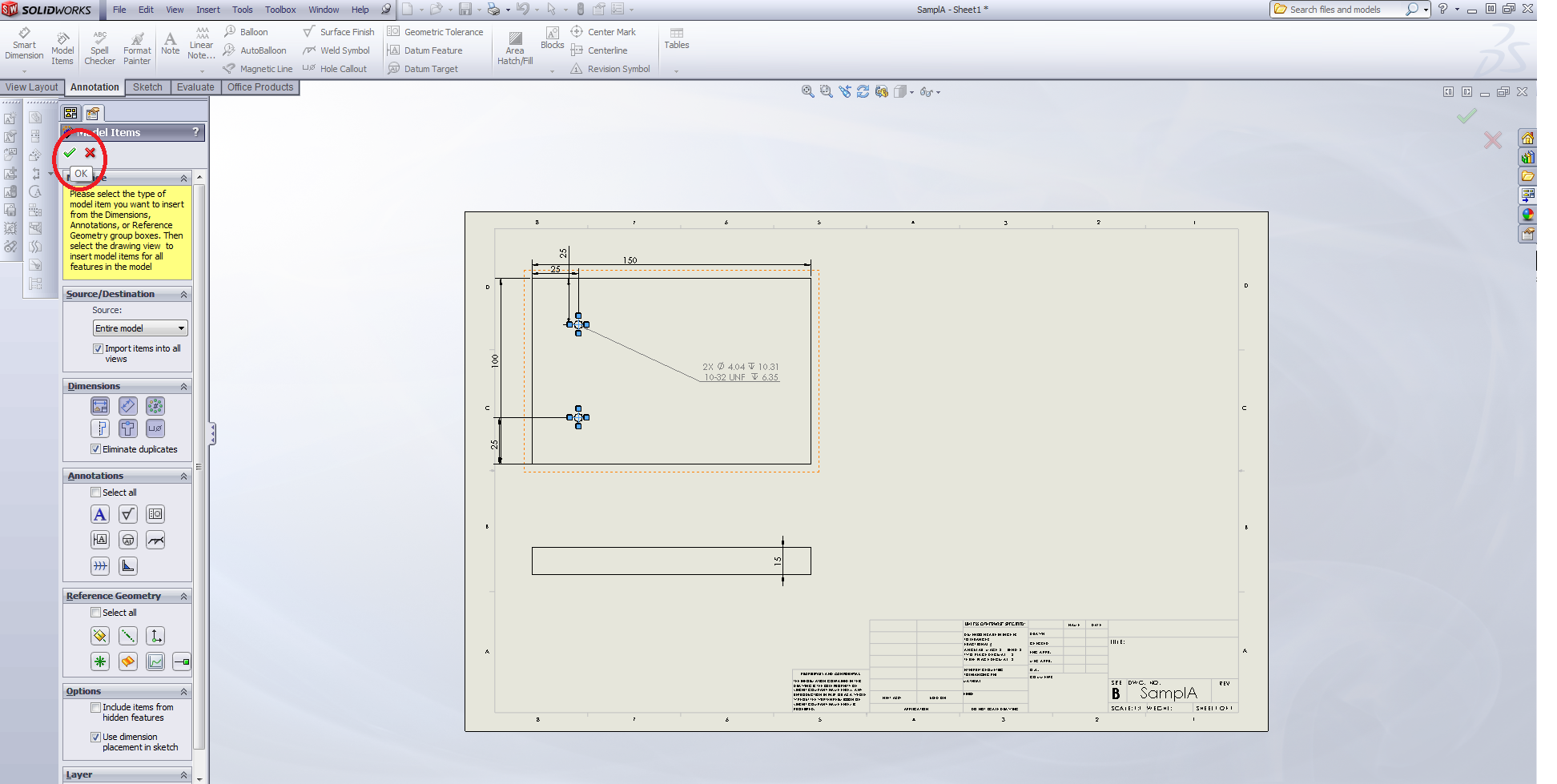
And that’s it. All the dimensions that you defined or used by default have just been committed to your 2D drawing with each view and feature being labeled as it is. Now let’s go see a few other options.
Misc. and Extra Features
Selecting Only the Wholes or Particular Features
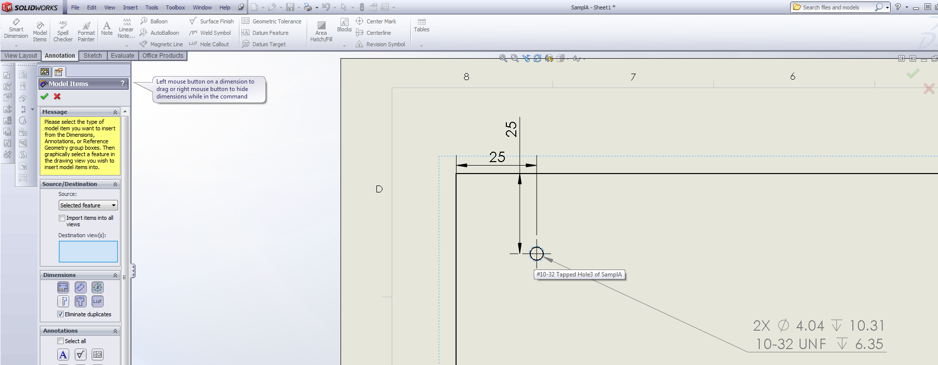
To make sure only a single feature is selected for dimensioning, we can simply go into “Model Items” and select the “Selected Feature” option for the source preference. With that, do not select anything but the feature directly. Upon selection, the features orange outline will turn blue, meaning that the feature has been selected and the function committed as can be seen below.
Call Out Annotations Without Marked Dimensions
If you’d like to have a call out only, and exclude the dimension markings, it’s possible with the “Dimensions” options selected as can be seen in the left column below:
Notice how only one option is selected. That is the call out option. The rest are disabled and vice versa selection will alter the kind of views you get.
Importing the Dimensions to all Available Views
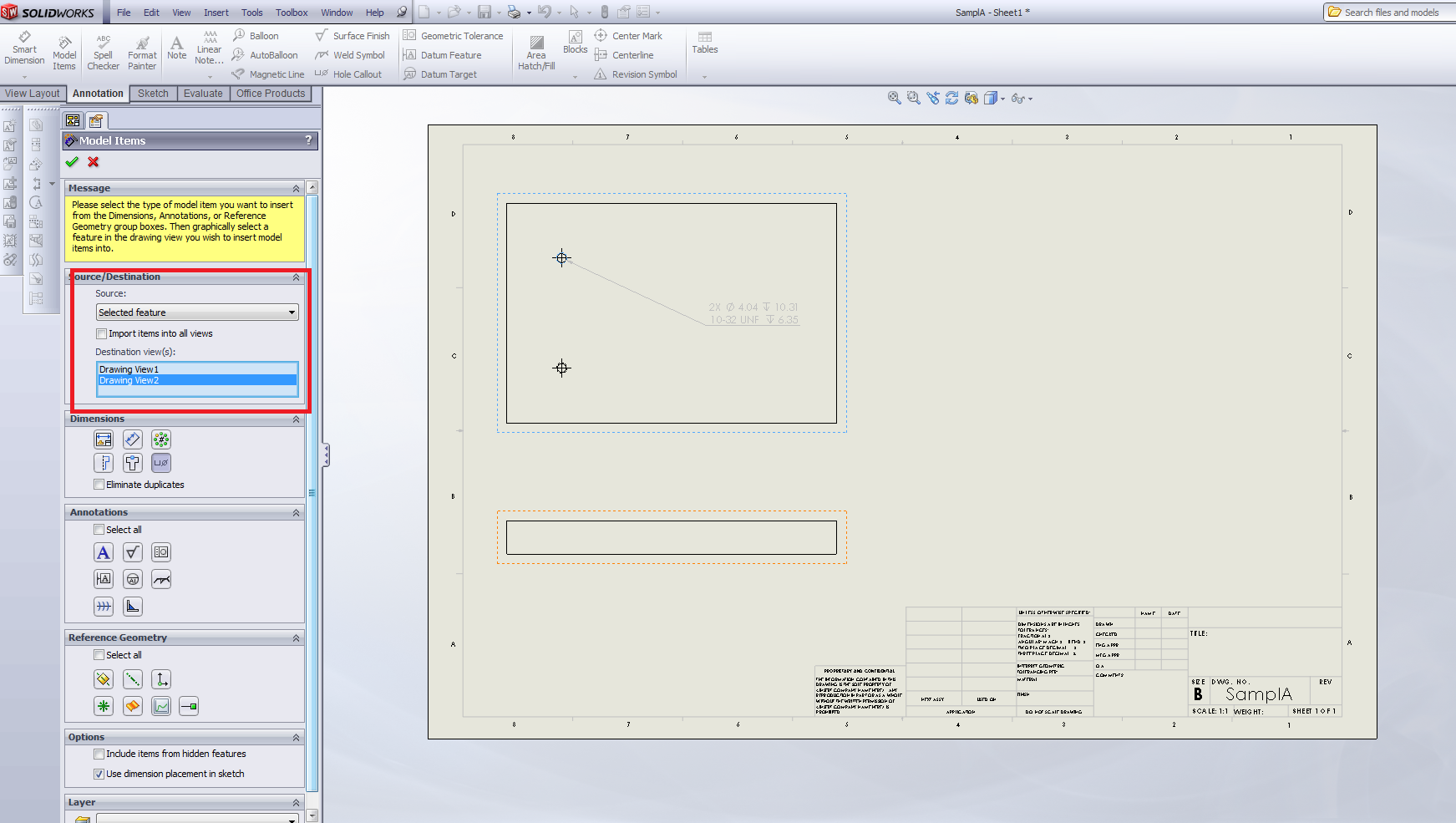
When you have multiple views in place, one quick and obvious way for displaying all dimensions on all views is to use the “Import items into all views” option. But in the case, you wish to show the dimensions on only a few views, select the views once and (as can be seen below) all the views will get highlighted on the left hand side. Select one or more views here, to dimension those views as opposed to all.
Dragging and Copying Dimensions
Once you’ve added, the dimensions to one view, having left out the other view for whatever reason, you can still copy or drag the original views dimensions to the new view. Here’s how:
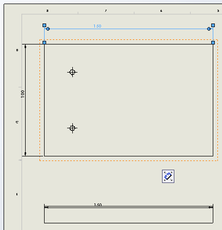
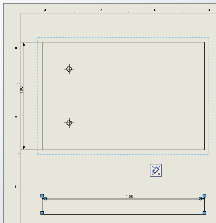
Copy – CTRL + dragging the dimension
Move – SHIFT + dragging the dimension
In the below two screenshots, the first one shows the dimension being copied while the second shows the dimension being moved.
Conclusion
You might have noticed the improper placement of dimensions where some of them seem to be interfering with other dimensions. To make sure all the dimensions are aligned when you apply the “Model Items” command, try to arrange the same dimensions properly while 3D modelling because those are the dimensions that get placed in the 2D drawing while using “Model Items” command. And there you have it, auto dimensioning in SolidWorks, the right way. Tinker with the options to see what else you can achieve, but rest assured, the days of manually dimensioning each face and edge are surely over.