In this tutorial, we’ll be taking a look at creating a basic weldment profile in SolidWorks. Weldment profiles allow you to easily create welded structures such as metal frames, and define the cross-sectional area for the members used to create such structures. SolidWorks has a pre-defined library of profiles available for you to select from, but you are also able to create your own to work with. That’s the goal of this tutorial, so let’s get started!
Create a New Part
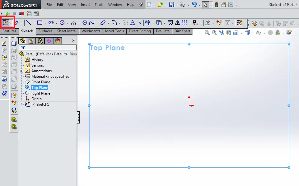
We’ll start by creating a new part. Select the Top Plane, and create a new sketch.

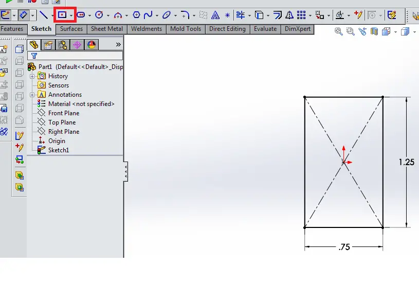
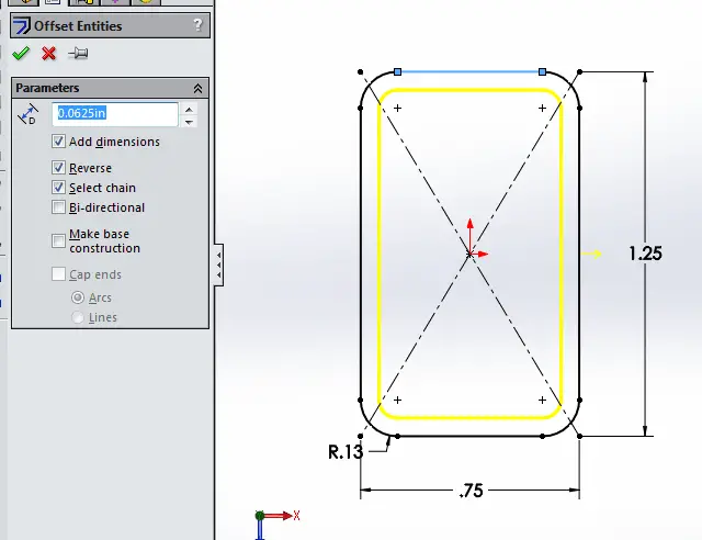
On this plane, sketch the cross-sectional profile of the custom weldment profile. In this case, we’ll make a rectangle with a height of 1.25” and a width of 0.75.”
Add Fillets
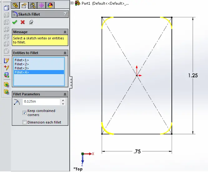
Next, we’ll add fillets to the corners using the Sketch Fillet tool. Size these fillets to be 0.125,” and select each line in the rectangle to form rounded fillets at each of the four corners.
Now, select the Offset Entities sketch tool from the toolbar. Specify an offset of 0.0625”, and select the profile you’ve drawn. Select the Reverse check box to be sure that the offset occurs inside the dimensioned profile. Select OK.
So far, you’ve created the cross-section for the weldment. Now, we need to place it in the appropriate directory to be able to use this custom weldment as a Weldment Feature in SolidWorks.
Saving as Lib Feat Part in SolidWorks
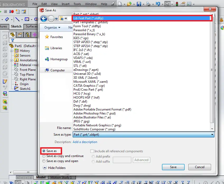
Start by saving this part as a “Lib Feat Part.” Click File > Save As and select Lib Feat Part from the drop-down menu. We’ll name this part “Weldment_1.25X0.75.” Don’t click save just yet –
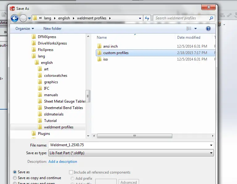
We need to navigate to the right directory to save off this feature. On most installations, this can be found in the Installation Directory, and then \lang\<language>\weldment profiles. Once you’re in this directory, create a folder called “Custom Profiles,” or something similar. Then, within this new directory, create another folder called “my weldments” or “Rectangular Profiles,” or something similar again. Now, save the feature in that new directory! We’ll see why it was important to create these subdirectories later.
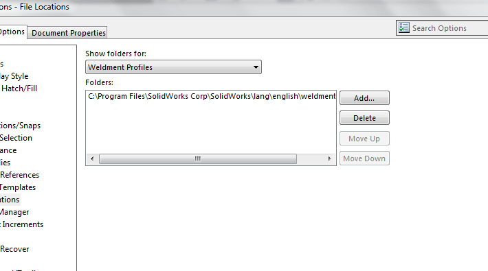
(Note – You will need to make sure that the Weldment Profiles folder you are saving your new weldment profile into is accessible by the software. To check this location, or to add a new location, select Tools > Options > File Locations > and select Weldment Profiles from the drop-down menu. Verify this location is the parent directory for all weldment profile directories, including the custom directories you have just created. )
Create a Basic Structural Member
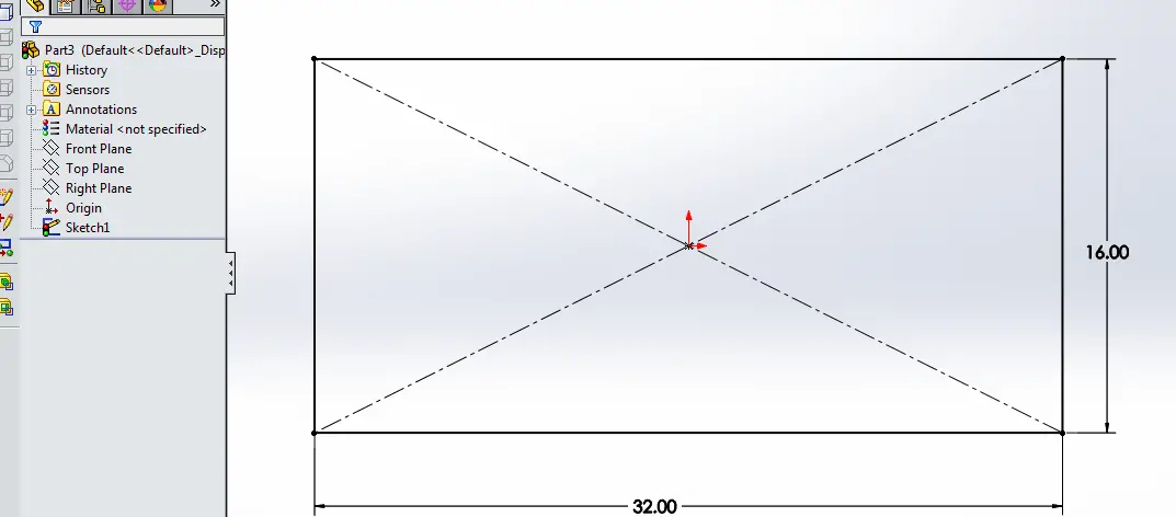
Now, we’ll create a basic structural member to test out the custom profile. Create a new part, and sketch a rectangle on the top plane. In this example, I’ve dimensioned the rectangle to be 32 inches wide by 16 inches tall.
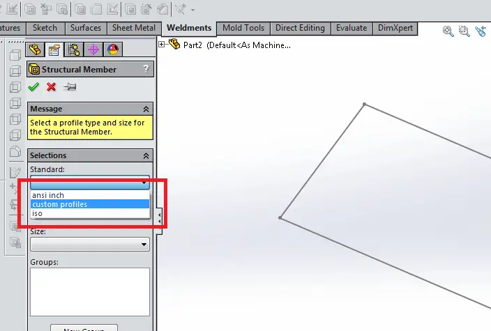
In the Weldments toolbar, select the Structural Member feature. From the drop-down menu, select the new “custom profiles” option for the “Standard” selection, and “my weldments” for the “Type” selection. These point to the custom directories you created previously. They will carry the name of your custom directories.
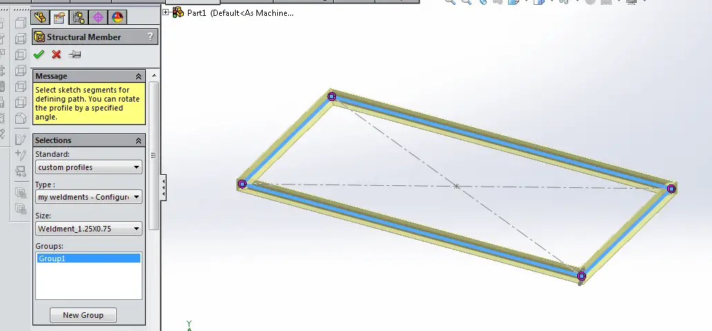
Select the entire rectangle as the selection for the “Groups” field.
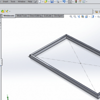
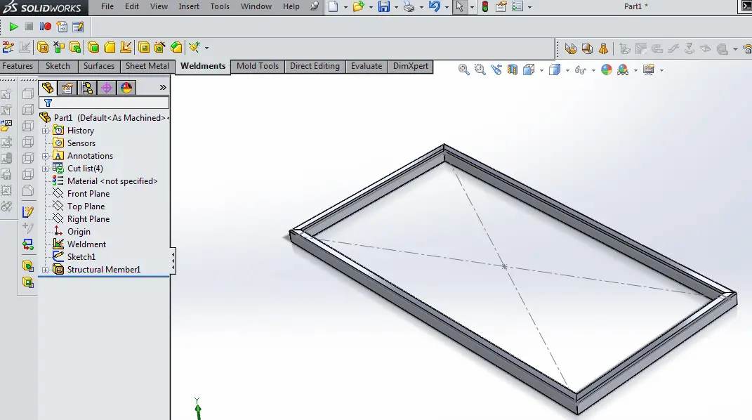
And, there you have it! If you’ve completed everything as described, you should see your custom and basic weldment profiles in SolidWorks similar to the one below:
Make sure to check out similar tutorials by going here.