
ANSYS HFSS software is one the commonly used modeling software for simulating 3D electromagnetic wave propagation. It is one of the essential tool for engineers involved in project in the field of high-speed electronic and high frequency components.
Here is a step by step HFSS Antenna design tutorial performed for the sake of letting beginners smooth their first contact with Ansys HFSS.
Of course this design comes after the theoretical part, since all Antenna design made in HFSS comes as a result of theoretical calculation previously made so to find the values of the antenna to be modeled.

The following tutorial shows you how to design an antenna from the starting point to simulation.
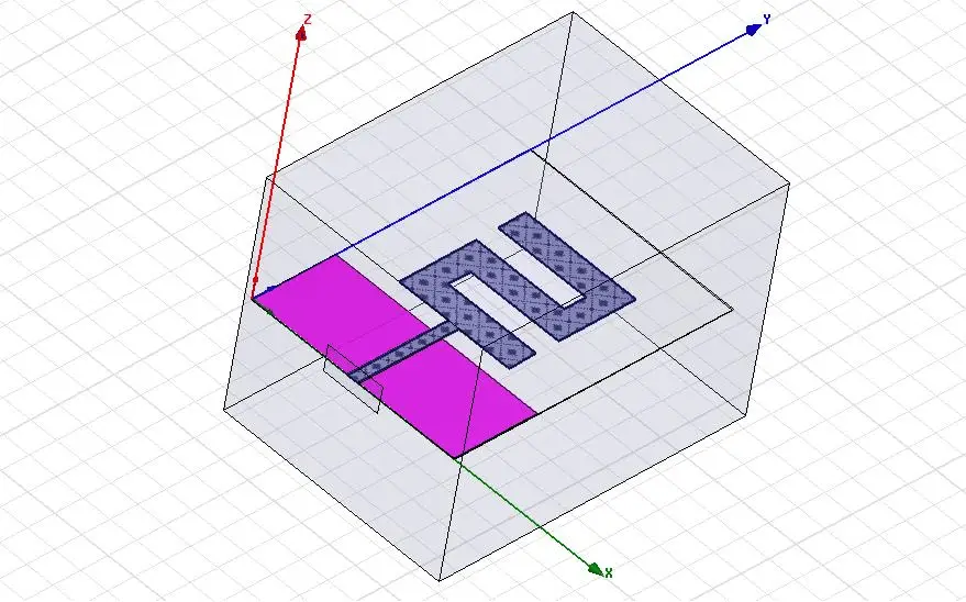
Here is the antenna configuration

It is a Z shape antenna with a CPW (Coplanar waveguide) transmission line.
For convenience, you have to start the HFSS antenna design by working on dimensions of your transmission line, Here we are working with a 50 ohms transmission line, and its return loss is simulated beforehand.
You should find equation related to the specific transmission line you are using in your design, and work out the dimension it is to have, simulate it in HFSS and plot the return loss to confirm your transmission line works the way it should.
So when you are finally coming to design and simulate your antenna, your know your transmission line works fine.
HFSS Antenna Design
The whole simulation need following elements
- Waveport
- Transmission line
- Radiating element (Antenna)
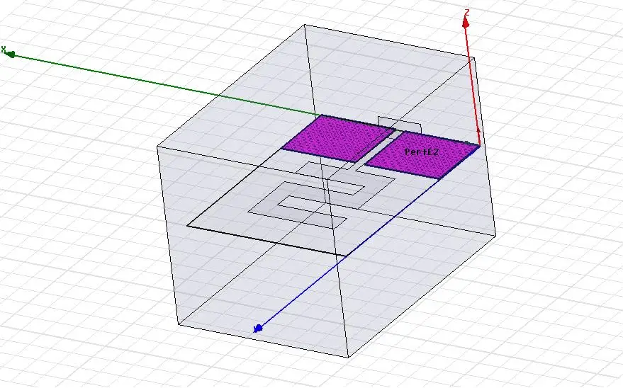
- Ground plate
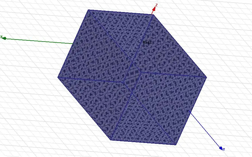
- Radiation box
Waveport
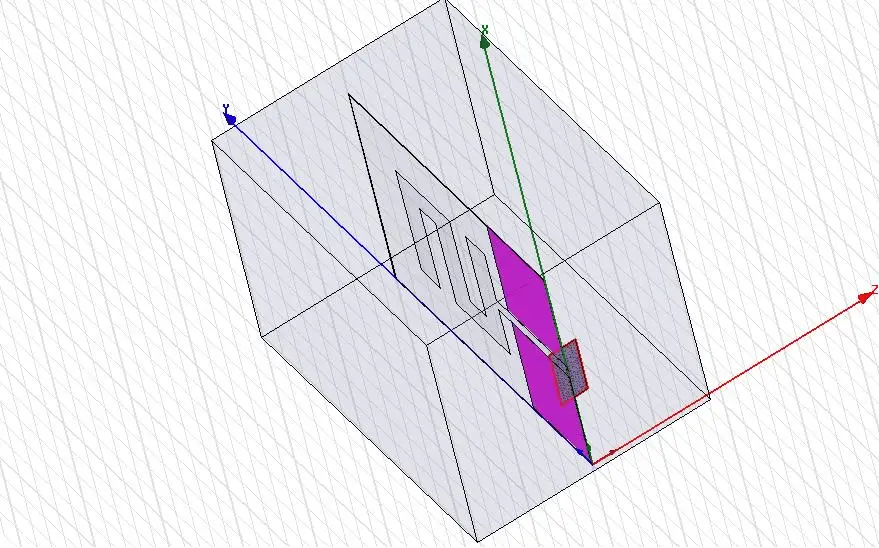
Radiating element
Parallel ground plate
Radiation box
Plots
Simulated Return Loss of the antenna
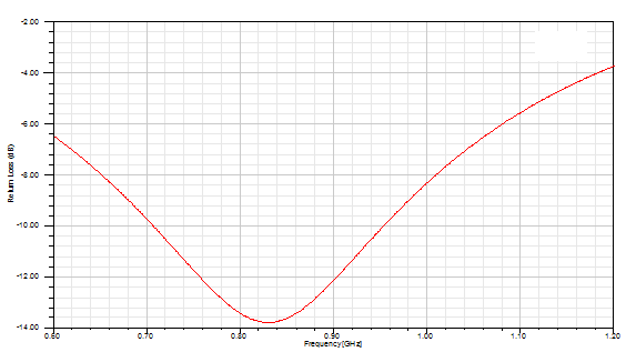
Simulated 3D Radiation pattern of the antenna at the resonant frequency of 900 MHz

This Antenna can further be optimized for a better Return loss.