After you are successful in creating a schematic file in Eagle CAD, it is time to learn how to add a part. A part refers to components such as resistors, capacitors, or even ICs such as microcontrolers. Even GND (ground) and VCC (voltage input) are technically parts when it concerns a computer aided design software for PCBs. The Eagle’s ADD window will be explained in detail in this tutorial. You can check out the previous tutorials to understand how to create a schematic and also the explanation of menus and toolbars in the software.
Let’s begin. I will show you the different options available in the ADD window of Eagle and how to find the right part. I will use a resistor as an example since it is the simplest to explain. However, this tutorial can be applied to any part in Eagle.
What will you learn?
The table of contents below outlines exactly the topics covered in this tutorial. You can skip to a specific topic by clicking on it. In general, I will teach you how to add a part into a schematic for the software, Eagle.
[toc]

How does the ADD Window Work?
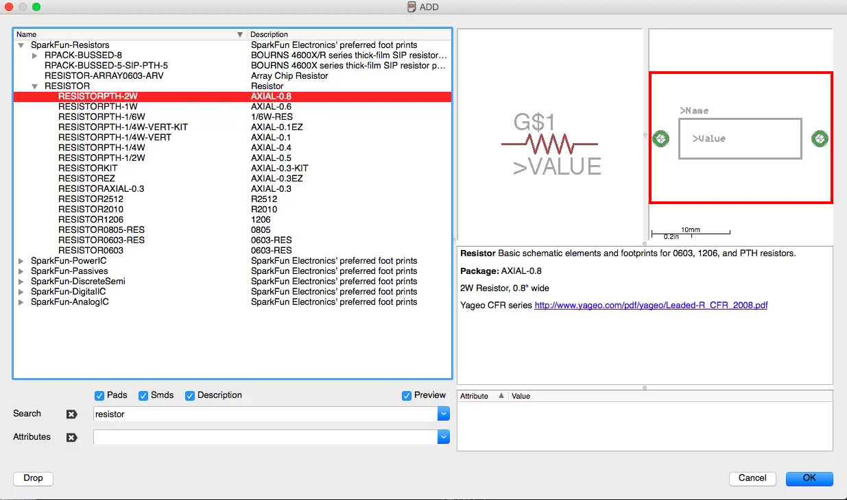
The ADD window is by far the most important aspect of Eagle. The ADD window has 5 sections that I will explain. Please refer to Figure 1 below for the section numbering.
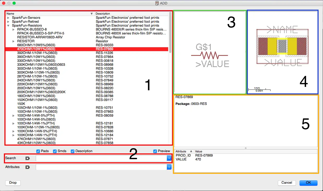
Section 1 – Available Libraries
In this section, you will see all the libraries that have been added to Eagle. I only use the Sparkfun libraries, however, you may have more libraries. If you expand a library, you will see several parts you can add to your schematic. Note that it will be difficult to find a specific part if you have many libraries. Thus, the search function comes in handy.
Section 2 – Search
By using the search, you can find exactly the part needed. For example, I can type ‘resistors’ and obtain a list of all resistors I have available in the libraries. As you can see in Figure 1, after clicking on a part, in this case a resistor, you will see the symbol, footprint, and descriptions.
Section 3 – Symbol
In this section of the ADD Window, you will see the part’s symbol diagram. This is what the part will look like in the schematic. Obviously, for a resistor, you have 2 pins to connect too. In other cases, you may have 3 to as many as 128 or more pins. It all depends on the part you choose. I recommend to go through the libraries to see the different symbols available. Get familiar with this window because it will be used in every PCB you make.
Section 4 – PCB footprint symbol
To the right of the symbol section, you will see the footprint section. This shows the physical footprint of the part on a PCB board. There is also a scale (1 mm) showing the relative size of the footprint. In addition, the footprint shows red-filled areas. These areas represent the copper pads that will be placed on the PCB so you may solder to it. You can see an example of this in the image on the right in Figure 2.
As a sidenote, Eagle software takes the physical part and creates a 2D CAD layout of it. This CAD layout can then be positioned on the PCB to your liking.
Section 5 – Description
When you choose a part, you can see the description in this section. At the minimum, it will show the part name and the typical size. Any additional information provided is optional by the manufacturer or designer.
Which part should I choose?
This is a question that I get asked by people. If you browse through the Sparkfun or other libraries, you will find several options for the same part. Which one should you choose? It depends. I will discuss how to decide on the footprint of a resistor, however, such decisions are also relevant for other parts, e.g. ICs.
Do you want to use a Surface Mount Device (SMD)?
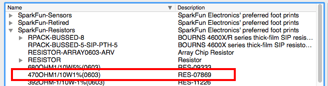
In a previous tutorial, I mentioned that most of the specifications, for example the value of the resistor, are irrelevant because you can change them. If you look at Figure 3, I chose a resistor that has a value of 470 ohm, maximum power of 1/10 W, and a tolerance of 1%. Most importantly, the last specification shows the footprint size of the resistor. Typical sizes are 0402, 0603, 0805, 1210, and others.
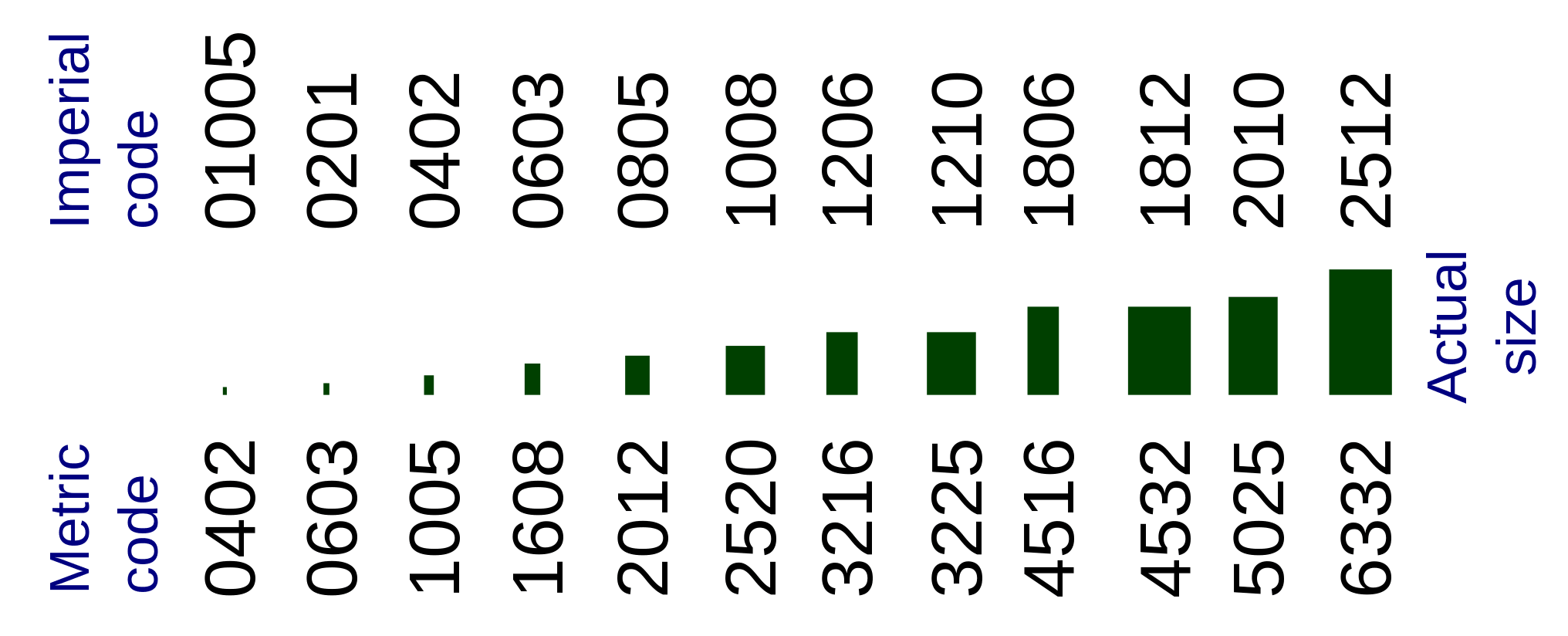
Check out Figure 4 for a chart showing the physical sizes and their corresponding footprint values. I refer to the Imperial Code, when stating values like 0402 ad 0403, because it is widely used by the industry.
In short, pick a size and ignore the other specifications in Eagle. The specifications are usually used to create a Bill of Materials (BOM) of all parts in your PCB. You can always go to your favorite vendor for electronic components, e.g. Digikey or Sparkfun, and look for the specific footprint size you need. After that, you can choose the value, voltage, wattage, and other options. This is what works for me.
If you are creating your first PCB, I recommend a larger footprint. The 0805 resistors and capacitors will be simple to solder to the board. As you gain more experience, you can decrease the size to 0402.
Take it slow and choose Axial/PTH
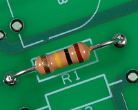
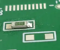
For beginners, a SMD resistor can be difficult to solder. However, most beginners are experienced enough to manage typical axial resistors. These are resistors with long leads as shown in the image on the right in Figure 5.
You can actually create a PCB with these resistors. When choosing the resistor, make sure to pick the PTH or Axial footprint size. An example in Eagle is shown below in Figure 6.
How to Add a Part to the Schematic
Now that you have a basic understanding, you can begin adding parts to your schematic. I will use a resistor as an example.
First, I like to use the search function (Section 2) as an easy to way to find the specific part I am looking for. You can use the menus as well (Section 1). To add a part, follow these steps:
- Find the part, e.g. resistor
- Find the correct footprint size, e.g. 0805
- Select the resistor
- Check the symbol and footprint to make sure it is the correct part
- Check the description to double-check the size
- Click on OK
- The part will now be under the control of your mouse cursor. Choose a location on the schematic and click. It will be placed in that location.
I also show these steps in more detail in the video at the bottom of this article. Be sure to watch that.
Video Tutorial on How to Add a Part
This video tutorial covers additional material about the schematic window and adding parts.
Final Thoughts
This tutorial discussed how to add parts into your schematic. I used a resistor as an example but this tutorial can apply to any part you would like to add. In the video, I also discuss adding capacitors. Once you are able to add parts, you can continue to the next tutorial. Good job!
Did you have any difficulties with this tutorial? Please share your thoughts and/or difficulties by leaving a comment below.
Leave a Reply