In this tutorial, we’ll create a basic spur gear using SolidWorks. The main tools we’ll be using here to create the gear are Extrude Boss, Circular Pattern, Extrude Cut, and Fillet. When we’re done, we’ll have a spur gear that you can easily modify and work with. Let’s get started!
What will you learn?
In this tutorial, you will learn how the following things below. If you are interested in a specific topic, you can skip ahead by clicking on the topic.
[toc]

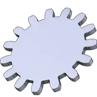
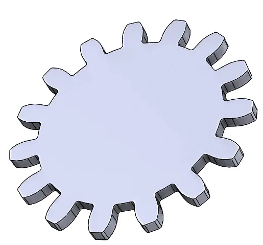
At the end of this tutorial, you will have create the spur gear shown below:
Note about Involute Gears in SolidWorks
Although a spur gear may look like a relatively simple component, it needs to be designed properly in order to work! Gear dynamics are fairly mathematically involved. A thorough look at the geometry and mechanics of an involute gear profile is beyond the scope of this tutorial. For now, follow along with the steps to create the geometry, but if you are interested, information about this type of gear design is widely available in the literature and online. A deeper understanding of this material is worthwhile and crucial for designing custom components!
Create the Sketch
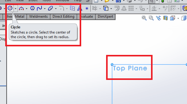
Create a new sketch on the Top Plane. Select the Top Plane, and then the Circle command.
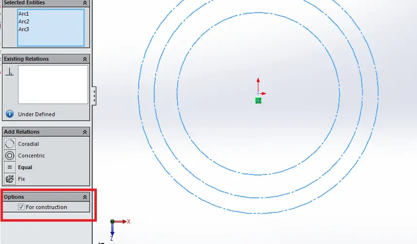
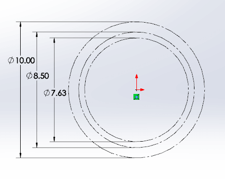
Now, sketch three concentric circles about the origin. Select all of these circles so that they are highlighted, and make the circles construction geometry by selecting the “For construction” check box in the lower left hand side of the screen.
Dimension the circles as shown in the illustration below.
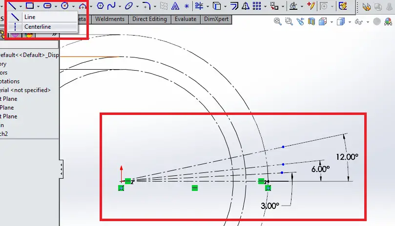
Now, add four centerlines starting from the origin, starting with a horizontal line, and dimension them at the angles shown in the next image.
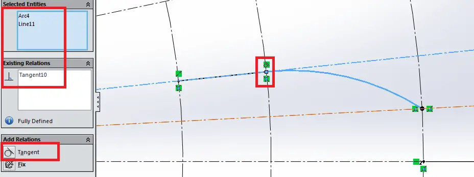
Now, zoom into the area where your four lines meet the circles. Select the 3-Point Arc sketch tool, and sketch an arc starting at the second line from the top, second circle, extending to the third line from the top, third circle. Now, hold the CNTRL key and select this new curve and the second line from the top, and select the Tangent relation. See the image below.
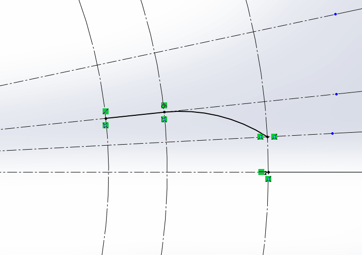
Now create a straight line connecting the left point of this arc with the smallest circle. Ensure the end points are coincident with the guide circles, and your sketch should now look like the sketch below.
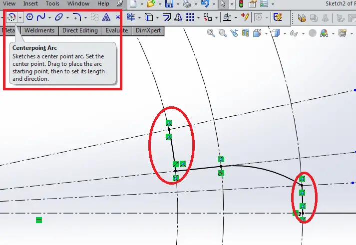
Add two Center Point Arcs about the origin to the sketch, tracing portions of the guide curves connecting the points shown in the following image.
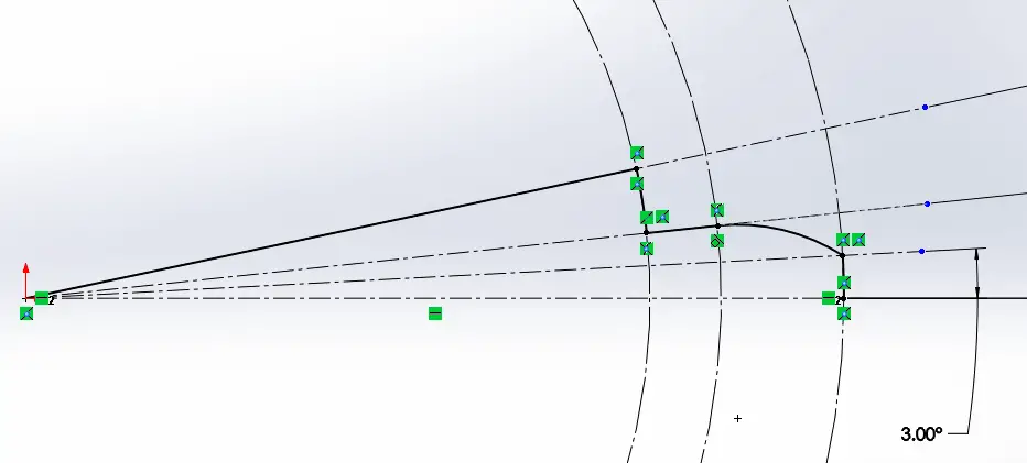
Finally, use the Line tool to trace the top line from the origin to the sketch endpoint, as shown below.
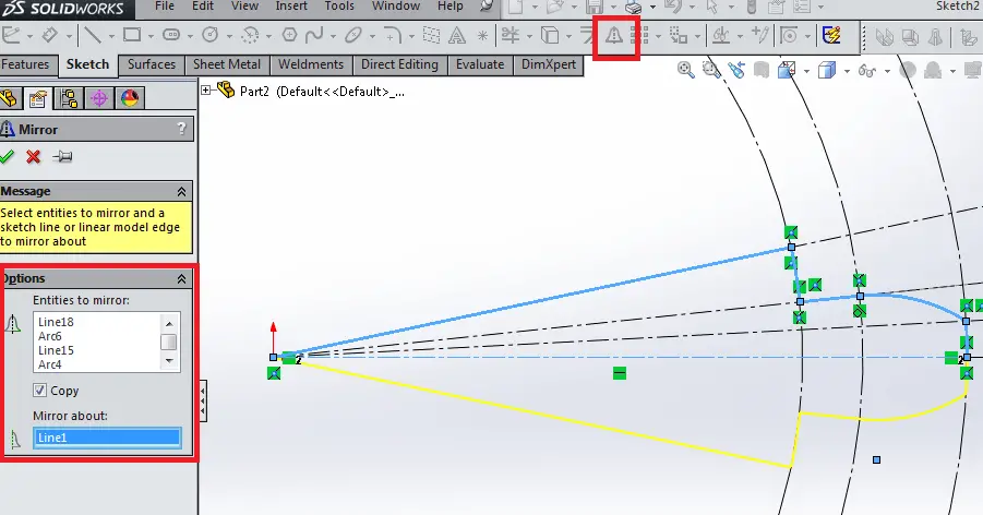
Now, use Mirror Entities to select the five solid lines and curves you’ve drawn, and mirror them about the horizontal guide line. See below.
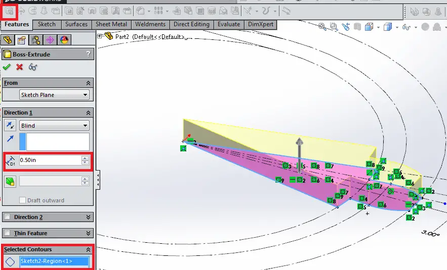
Select OK. Select the Extrude Boss/Base feature, and select the area inside the solid profile you’ve created. Specify a value of 0.50 in for the gear thickness. Select OK. You now have the basic shape of a section of the gear!
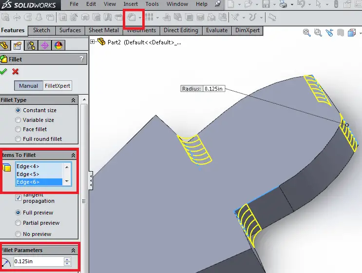
Now, use the Fillet tool to add radii to the four edges shown. These features make the gear more machinable using a mill. Select OK.
Add Patterns to Spur Gear
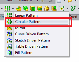
Use the Circular Pattern tool to pattern your gear section about the edge of your gear section that runs through the origin. The gear section will have 15 instances to complete the 360 degree pattern. Select “Equal Spacing” and be sure to select both the Extrude feature and Fillet features in the solid model to pattern.
Select OK. Congratulations! You’ve created a basic involute spur gear profile. Feel free to add features such as a cutout for mounting the gear, or play around with the values provided to customize the shape to suit your needs.
Final Thoughts
In this tutorial, you learned how to create a spur gear in SolidWorks using the Extrude Boss, Circular Pattern, Extrude Cut, and Fillet features. Even though, creating spur gears requires some mathematical knowledge, this tutorial creates a basic gear that you can learn from.
Check out the other SolidWorks drawing tutorials to learn more.