So, you cannot find an STL of a model you want to print or you have a custom object in mind but don’t know if it can be printed. Well, fear not! This article is meant to show you how to design any object so that it can be printed with your desktop 3D printer! It will cover the basic design elements and tricks to use in your models, show how to fix broken STLs, and suggest programs for the printer enthusiast to use that will put the entire process of making – from design to manufacture – in their hands.
What You Will Need
 All you will need to make your own custom objects is a computer that can run any of a number of CAD or 3D modelling software and the software itself. It also helps to use a program like Cura or MakerWare that displays the final 3D file you make scaled to your printer’s work area and check for any last minute mistakes.
There are plenty of powerful 3D modelling software packages available online. CAD programs like Solidworks and Autodesk’s Inventor and Fusion 360 are available for free or heavily discounted to students and hobbyists. Check out our head to head comparisons of different CAD softwares, e.g. SolidWorks vs Inventor, Other CAD programs like Google Sketchup (you will need plugins so make sure to check out top plugins for Sketchup) and OpenSCAD are less powerful but free. Basically any program that can export .STL files will work.

Another option is to use 3D modelling software like Autodesk’s 3DS Max and Maya or the open source Blender (see our comparison between AutoCAD vs Blender). These free-form modelling and animation programs will not be much help for an engineering model, but are great for creating, posing, or fixing more complex, organic models for printing like game characters, ancient statues, or vehicle models.
It also helps to have a measuring tool capable of at least measuring tenths of millimeters. You can pick up a decent set of calipers from your local hardware store for cheap, and it is a worthwhile investment for anyone who plans to print objects meant to fit anything. Calipers also help test your printer to make sure it is printing correctly by double checking the dimensions of parts are within normal tolerance.
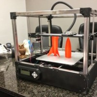
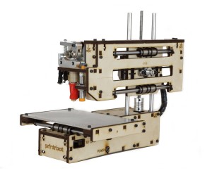
Most important, you will need a 3D Desktop printer to test your CAD project. You can find a list of the best 3D printers here.
Designing Objects for Printing
Traditional manufacturing techniques use a piece of stock and subtract material until the final shape is achieved. 3D printing differs in that it starts with nothing and adds material until the final shape is achieved (hence the term additive manufacturing). This allows 3D printers to produce shapes more difficult to produce with other methods, such as internal cavities or complex curves.
One of the most important things to consider when designing anything to be manufactured are the limitations of the manufacturing process. Some shapes may not be able to be machined; some materials may not work with one manufacturing process as well as others; some manufacturing methods take much longer than others. 3D printing has limitations just like any other manufacturing process.
A 3D printer’s most obvious limitations are the print volume and the minimum layer height. The print volume dictates the maximum size a single part can be, while the minimum layer height dictates how fine the details of the model are. Layer heights above .2 mm (200 microns) are considered coarse, while layer heights below .1 mm (100 microns) are considered fine.
When designing an object, keep in mind what layer height you plan to print with and how well your printer’s results are at that setting. Simple test prints offer good reference points to see how well a printer performs and what level of detail to expect. Try using a model other than a cube to test your printer with; such as a small turtle, a pin from your favorite TV show, or any number of small models available online.
As for your printer’s print envelope; if you plan to make an object that fits inside, you need not worry. But if you plan on printing something larger than your printer allows in one print, you will need to slice it up into chunks. The best way to do this varies from model to model. For statues or character models, simply slicing the model along planes will do, and the final parts can be glued together. This can be achieved in most CAD programs by extruding a rectangular shape over your model that keeps only what is inside the shape.
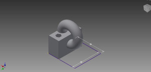
A part that doesn’t fit in inside a 25 x 25 x 25 mm print volume can be trimmed to fit with one command. The excluded part can be printed separately and glue on.
Another method of keeping individual parts inside the print volume is to simply design them that way and include ways of attaching the parts later on. An easy way to do this is to include holes for screws to fit through that are perpendicular to slots for nuts to slide into. Parts can be made to interlock as well, but another limitation of 3D printers will get in the way of designing something like a clip on a backpack: overhang.
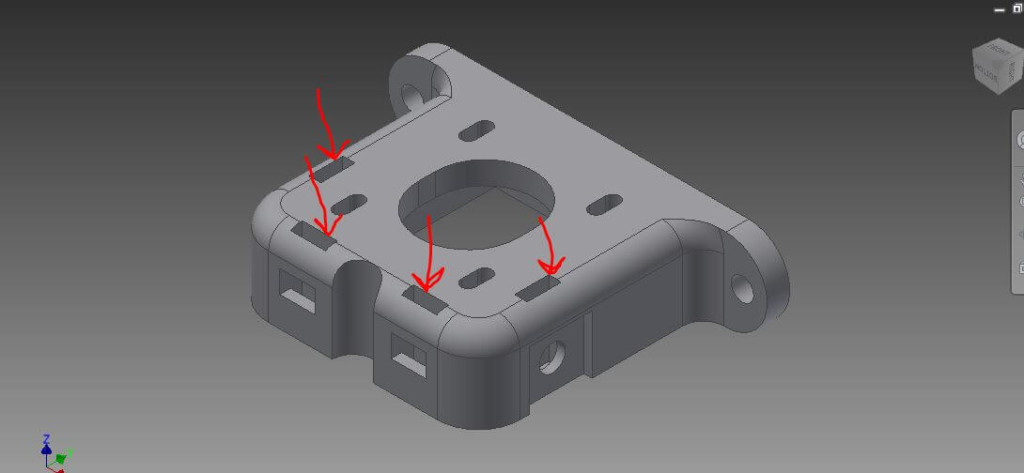
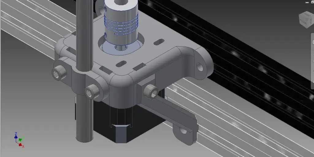
A part designed to be attached to others with nuts and bolts. The red arrows indicate slots for the nuts which cannot be seen in the assembled picture.
Overhang is a section of a model that hangs over the print bed with nothing supporting it. It may be the single most limiting factor when printing anything; the plastic being deposited must be supported underneath or else it will droop, deform, or simply not form the correct shape. Most printers deal with overhang by automatically including support material under any face of the model that is within a certain angle over the build plate. This usually works, but uses more plastic that needs to be removed later on that will sometimes leave behind unwanted rough spots on a model.
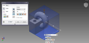
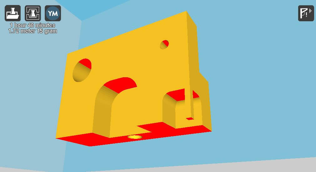
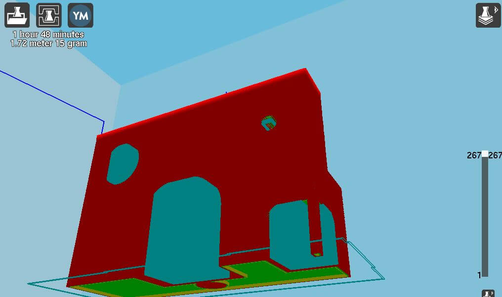
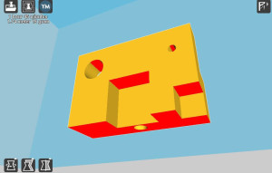 The red faces indicate overhang extreme enough for the program to automatically create support material. In this example the bottom face touches the build plate and won’t have support materials, the small hole won’t need it as much as the larger, and the corner overhang will need it or else fail entirely.
The best way to combat overhang on your model to design the part from the ground up to eliminate overhang wherever possible. Many printers have fans that cool the plastic filament as soon as it is deposited, allowing short bridges of material with little to no deforming without support material. If you keep overhang between two large sections of a part small, it should have no trouble printing. For larger sections, try rounding out the corners, effectively building an arch. This gradually extends the part out and reduces the final distance overhang needs to cross while giving it added strength.
The image on the top shows different version of the above model that rounds some of the corners to reduce the amount of overhang and adds support to the corner to make it printable. The image on the bottom shows the model in red and green and the automatic support material in blue.
Another limitation found in printers is the heat needed to melt the plastic in the first place. Edges of parts cool faster than the middle, and the top area where the printer is working is warmer than the bottom that has been cooling for hours in some cases. Cooling fans help reduce the temperature difference at the top, and heated beds warm the plastic at the bottom to reduce temperature variations that cause parts to warp and peel up from the print bed. So why should you worry about the printer’s temperature when designing a part?
Let’s say you are designing a church, castle, or city skyline with lots of tall, thin spires. As the printer moves between each spire excess plastic begins to form strings between them, like spider webs, and as more spires are topped off and the printer is moving between fewer and fewer spires, each spire has less and less time to cool off. Plastic begins to slump or cling to the print nozzle instead of the part, colliding with other areas of the part and resulting in what is known as a “Rep Crap”. To avoid Rep Craps, try to avoid making designs with tall, thin sections smaller than about 1 mm. It is possible to go that small for short distances; but depending on the abilities of your printer, do not expect the plastic to be very strong or very straight.
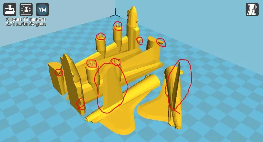 The image above shows an airplane model that has been sliced up to fit in a small printer. The blue squares represent 10 mm, the parts circled in red are either too thin or small to print correctly at this scale or have problematic overhang.
Speaking of strength, one of 3D printing less known limitations is the difference in strength in the X-Y and Z directions. In a nutshell, the gap between each layer is a weak point that can result in the layers splitting when too much force is applied, typically less force than would be needed to break a part in the X-Y directions. Printing at higher temperatures can strengthen the bond between layers; however this will result in runnier prints and less detail. If you are designing a part that will be subject to high forces, you need to try orienting the part for printing so that the forces it will be subject to do not act in a way that will pull the layers apart.
Most of the time your prints probably won’t be getting crushed or pulled apart by more than a few dozen pounds, but screws often apply enough force when overtightened to split layers and ruin a part. To avoid this, do not over tighten any screws used for fastening parts together, and use washers to spread the force over a larger area. Lining screw holes up with the Z-axis whenever possible not only serves to compress the layers, but also eliminates possibly overhang by reducing the number of holes in the side of the part.
Tips and Tricks for Design
So now that you know the limitations of 3D printing and common ways of combating or avoiding them, what else can you do?
- Fillet Corners: Filleting or rounding corners is an easy way to add strength to any part when applied correctly. Adding a fillet to a corner in the X-Y plane will reduce the stresses there, and spread a shearing load over multiple layers instead of just one as a sharp corner would. Avoid fillets along the bottom edges of a part, as they allow the part to peel up from the print bed.
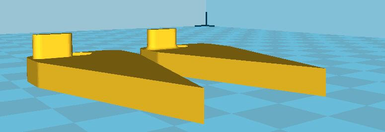
These parts use a wide pin that moves in a slot and are the same except one has a filleted edge where the pin meets the part and the other has a sharp corner. The pin with the sharp edge tends to break much more than the pin with the rounded edge in the same application
Designing parts with their own support material:
In some cases, you may not want a printer’s automatic support material in a certain area of your part. If you model support with the part, you can avoid the automatic supports or turn them off altogether. In some cases the support can become part of the model, such a character resting their arms on a pedestal or holding a staff or sword that touches the ground. For the most part automatic support material is well tuned these days to be easy to remove and leave little behind; but once again this is up to you and your printer’s capabilities.
Design wiggle room into parts meant to be fit together:
Compared to modern CNC milling machines, which can be accurate down to ten thousandths of an inch (three thousandths of a millimeter); 3D printers are not very accurate. The smallest feature a desktop printer can achieve is dictated by its layer height and nozzle size. The smallest Z feature is determined by minimum layer height (typically .1 mm or 100 microns for most commercial printers) while the smallest X-Y features are determined by nozzle size ( around .4 mm for most commercial printers). The accuracy these printers can place these features is much higher than that and is dictated by the types of motors used to drive the printer and the quality of materials, but with the way plastic expands after extrusion you cannot expect tolerances less than a hundredth of a millimeter from the best desktop printers. This can make fitting parts or inserting screws difficult. Again this varies from printer to printer but try adding about .1mm to the dimension of the screw hole or slot, while leaving a peg or insert at the exact dimension you want.
Know the conditions the part will be used in:
This is very important when designing a functional part. This should be taken into account when choosing the material you plan to print with more than the actual designing, but it is still relevant. A part for a printer that is near the print head, such as the X-axis carriage (the part that slides the extruder head in the X-axis) and the extruder block (the part that the extruder assembly is mounted to) is subjected to high temperatures in certain spots and can deform if those temperatures get too high. Thickening these parts should reduce immediate deforming due to heat, but will also allow the part to retain heat for longer. It is easiest to select a material that will stand the heat, like using ABS for a PLA only hot end or Metal for an all-plastic hot end. Check out an article on how to choose between ABS and PLA.
Know what is printable and what is not printable:
Thin, spindly parts with lots of overhang just won’t print, no matter what you do with them. Avoid parts that use these features and you should have no trouble with your designs.
Know your infill settings:
Infill is the plastic that goes on the inside of your part. The more there is the stronger and heavier your part is going to be, as well as the longer it will take to print. A good way to reduce infill but maintain strength is to increase the number of perimeters the printer does each layer. Two perimeters with about 25% infill can work pretty well. How this relates to design can be seen in thin walls and in the top and bottom of a print. Each perimeter is as thick as the nozzle of the printer, meaning two perimeters is twice your printer’s nozzle diameter. When designing a thin wall, or when placing a hole near the edge, keep in mind how many perimeters you will have there. A 2 mm thick wall with two perimeters on a printer with a nozzle of .4 mm diameter will have 1.6 mm of perimeter (two perimeters of .4 mm thickness on each side of the wall) and .4mm thick space for infill. Making the wall smaller than 1.6mm will likely result in fewer perimeters (depending on how your slicing program generates its tool path) and weaker edges. A 25% infill with these settings will also take around four layers at 100% infill to cover up without holes, so any section that is less than eight layers in thickness (four for the top and four for the bottom) will be at 100% infill regardless of the settings for the rest of the part.
Final Words
Designing parts takes a lot of trial and error to get right; you may go through a half dozen or more iterations of the same part just to fix issues you could not see while designing it, like a hole being too small for a bolt to fit through or too large to hold the bolt firmly in place, or a part just bring too thin and breaking when in use. Hopefully this article will help eliminate some of the error in your designs and make your printing experience that much more productive and effective.
Comments
One response to “How to Design For 3D Desktop Printers: An In-Depth Tutorial”
[…] interested on tips and tricks to actually design in software for 3D printing, check out this tutorial. For now, let’s go ahead and see what packages would be the best and […]