
Any 2D drawing or model that has been designed and is ready for 3D development usually requires some kind of preparation before we can begin the 3D design. This is because in 2D, the design cannot be realistically assessed, meaning only once a 3D model is created of the drawing, the finer details tend to show and, subsequently affect the quality of the work.
Drawings can be prepared for 3D development for a number of reasons ranging from game/film character development to construction related virtual designs. In the following text, we will see how the whole thing comes together.
Introduction
First off, this is a necessary task because of the fact that leading on, the design needs to be validated for its real-life authenticity. This means, the drawing needs to be tailored for AutoCAD processing as well 3D product design which will not compromise the drawing standards later on.

Closed polylines and correct layering are examples of techniques necessary for the successful renders. Moreover, the organization of the drawing elements greatly effects the output hence a clear view of whether the elements need to be separate entities or grouped objects, is essential.
First Things First
 Accurately drawn content is a must for 3D. For some projects, depending on the nature of the work and design, the complexity of the project makes it difficult for the designer to authenticate all elements before finalizing them. The 2D view not only limits your own decision making ability but can also hamper the subsequent 3D development and production process.
A good drawing or model will show up clearly in the 3D software once imported, and will not show rough edges, unbound or loose entities to name a few common problems. Once a drawing is imported, lack of proper judgment and hindsight render most drawings into a horrible 3D design and often require another go from scratch. Smooth designs and badly drawn geometry will always become more prominent in 3D.
The Complexity of Simplicity
Simplifying the drawing, or stripping it of unwanted content is the first step in the process of importing. Cleaning the drawing of all elements not needed, creates a separate, much more simplified drawing allowing the 3D designer to work with only the design and not with the miscellaneous elements that were added as viewing aids. This can include all the following:
- Purge all peripheral drawing elements
- Hide al the text used as annotations
- Set your UCS to World, in the case you had chosen another
- Bind your external references, so they don’t break when exported out
- Audit your drawing to make sure it has been stripped of everything but the main design elements
- Only once all the relevant elements are displayed, copy and paste them into a new drawing file using the original coordinates from the original drawing. That will make sure that the designer gets only the relevant material in a standardized manner, allowing them to start work as soon as the design is verified to be accurately built.
Common Commands
As with all Autodesk’s products, AutoCAD has a vast and powerful command line processor. A few commands that will be used multiple times, are listed below. Please remember, these are the building blocks of the whole design process and hence will be repeated frequently whether the design is simple and lengthy, or complicated and otherwise. Check out the commands here:
Standard Commands – Self explanatory |
Advanced Commands |
| Move | Extend |
| Rotate | Boundary |
| Copy and Multiple Copy | Fillet > Chamfer |
| Offset | Pedit |
| Trim | Manipulation of Vertex Handles |
| Snap On/Off | |
| Ortho |
Block Editing
 Blocks or other elements that get repeated often in a drawing may not always need to be present when exporting the drawing. This saves disk space and not to mention the memory required for processing. Also, a block may need to be replaced/dimmed out although its presence may serve as an important reference.
For this, when simplifying the drawing, elements can often be replaced with reference marks only when the new drawing is developed. For example, if you wish to remove the plantation that appears on your blueprints/floor plans, but obviously need for the location of the said plantation to remain visible, you can manipulate one element in a certain manner, and with macro-like behavior, update all the rest of the elements in the same block.
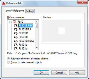
This requires that all block elements share the same block reference as this reference will be the focal point of the revision. This can be done as follows:
- Select one element of the block.
- Right click and select editing options. Double clicking should also open the “Reference Edit” window.
- Here, select the reference name, which will essentially select on element for you to manipulate.
- Once you click “Ok”, the block will be shown in an editor.
- Here, you can edit your block, for example adding text and a certain shape/mark to denote the plantation.
- This last step should be committed on either a newly, separate layer, or layer 0, saving which will automatically update all elements of the same block reference.
This will show the marked area for your blocks without actually showing the element, hence in the 3D modelling phase, you won’t have to actually work out the referenced elements, their references/marks can stay as they are for future reviews.
Importing the Drawings
For AutoCAD 2007 and Earlier Versions
For earlier versions of AutoCAD, the import DWG window is the best option for creating DWG files that will later be exported for 3D development. The window can be accessed from the File > Import menu, from where the “Select File to Import” dialogue allows you to select a host of options before final output. Although this is the obsolete version of doing things, because the software has come a long way since 2007, the options here can still be used due to their flexible nature.
AutoCAD 2008 & Newer Versions
With developments over 8 versions and upgrades in the software, the DWG import option has been changed to accommodate DFX exports also. The new dialogue box will show tabs and other options, from which the “Layers” tab will allow you to choose what to keep and what not to.
Once selected, head in to the “Geometry” tab to tweak options according to your requirements, following which, press of a the “Ok” button will import your drawing’s elements into a new MAX/VIZ format file, which can be used for exporting later. Verify all the elements and make sure you’re drawing is fit for 3D development.
Doing so, allows us to organize all elements according to a certain fashion, such as a predefined naming scheme that will allow the new designer to easily relate to the whole drawing. Once all of this is done, you will find that your new drawing has everything clearly marked on layer 0 with a clean and referenced element set that you can now turn into 3D.
Conclusion
Taking a 2D drawing from AutoCAD or any other package, and exporting it to a 3D development package will almost always have errors that need fixing.
A simple drawing, may be easier to clean up, but as the projects/tasks get more complicated, the above literature is bound to help you develop a drawing that will be easy to work with in the future. As stated above, not going through all this doesn’t mean your drawing isn’t worth the effort that you have already put in, but instead means that common errors and problems that you are likely to encounter in the future, can be avoided using this reference guide.