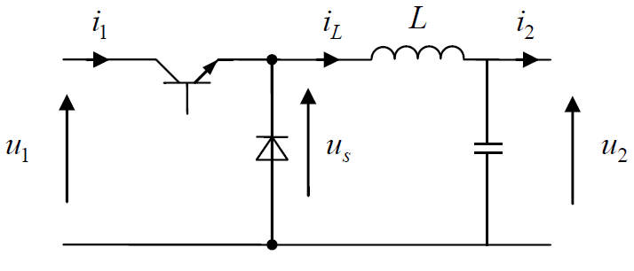
A Buck Converter is a DC – DC step down voltage converter (can also be considered like step up current converter) .
Here is how you can use Matlab to simulate a Buck converter (Note: In this post, we will consider switches as ideal)

In order to get this task done in Matlab we will need the following component from Simulink Library.
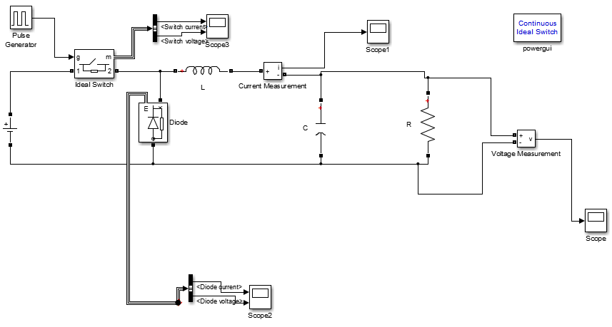
Design a Buck converter in Matlab
Main elements
DC voltage Source
Amplitude voltage: 190 V
A Pulse Generator
![]()
Amplitude: 1
Period (sec): 0.0001
Pulse width (% of period): 25
Phase delay (secs):0
Interpret vector parameters as 1-D: activated
An Ideal switch
![]()
Internal resistance Ron (Ohms): 0.001
Initial state (0 to ‘open, 1 for ‘closed’): 0
Snubber resistance Rs (ohms): 1e5
Snubber capacitance Cs (F): inf
Show measurment port: activated
A Diode
![]()
Resistance Ron (ohms): 1e5
Inductance Lon (H): 0
Forward voltage Vf (V): 0.8
Initial current Ic (A): 0
Snubber resistance Rs (ohms): 500
Snubber capacitance Cs (F): 250e-9
Show measurement port: activated
An Inductor, a Capacitor and a Resistor
![]()
L=200e-6
C=300e-6
(All these 3 components are being added by using the element below, you just need to choose one or more to be included in your block/element)
Additional elements
In order to visualize the behavior of different voltages and currents in the circuit, we will be using the following elements.
Current measurement
![]()
Voltage measurement
![]()
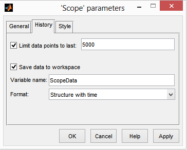
Scope
![]()
Parameters
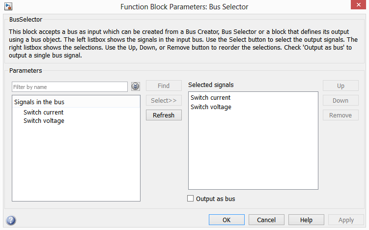
Bus Selector
![]()
Parameters
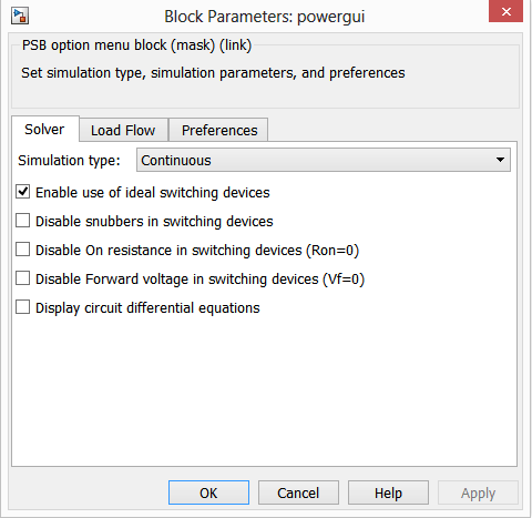
Powergui
![]()
Parameters
Opening Simulink Library and creating a new model in Matlab
By clicking on the icon shown on the picture below, you can open Simulink library
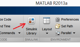
The following should pop up
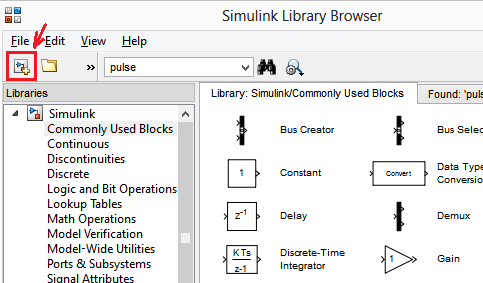
You can then easily create a new model with a click on the New Model icon shown on the image above.
After opening the new model, draw the following
Most of the element are in SimScape/SimPowerSystems and in Simulink Library. You can use the research bar to find element in the library as well.
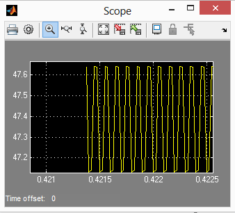
Run the model, and check different wave shapes on each on the scopes.
My output voltage shape looks like this
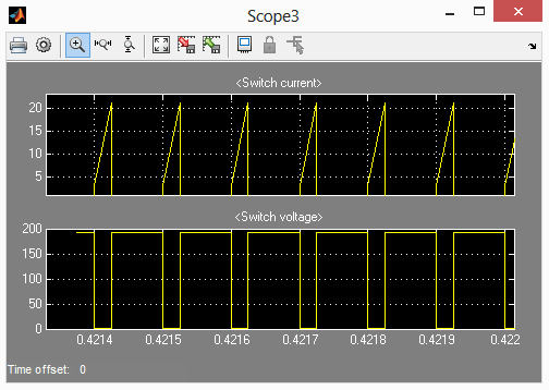
Switch Current and voltage
Comments
3 responses to “How to design a Buck converter in Matlab”
resistor value?
The resistor in the Simulink model represents your load. Thus, size the resistor for the current draw your load will typically have.
do you have the simulation for DC transformer model of buck converter ?