Tag: PCB Tutorials

How to Create a NEW Package in a Library – Eagle PCB
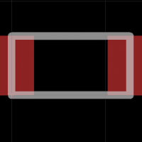
A package is a physical layout of the component, e.g. resistor, you are trying to create. This layout includes the dimensions of the part itself and the dimensions of the copper pads. With this information, a 2-dimensions CAD representation can be created in Eagle software, which will then be placed on the PCB. In a previous tutorial,…
Eagle PCB Tutorials and Design Exercises
The industry of Computer Aided Design (CAD) includes Printed Circuit Board (PCB) design. Most people that are around technology have most likely seen a PCB. However, they probably were unaware of what it actually was. In simple terms, a PCB is a physical board with electrical components which performs one or many electronic-based activities. I…
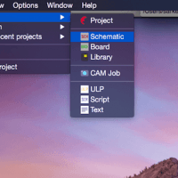
Schematic Options and Menus in Eagle PCB – Tutorial
In order to send a PCB for fabrication, the first step is to create a schematic. A schematic is visual representation of the electrical connections. In the previous tutorial, I explained how to create a new project and schematic file so check that out before continuing here. First, it is important to understand the numerous…
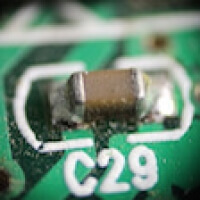
How to Add a Part in a Schematic – Eagle CAD Tutorial
After you are successful in creating a schematic file in Eagle CAD, it is time to learn how to add a part. A part refers to components such as resistors, capacitors, or even ICs such as microcontrolers. Even GND (ground) and VCC (voltage input) are technically parts when it concerns a computer aided design software for…