
Welcome to 2D AutoCAD exercise Day #17. It’s been more than a couple of week we are learning 2D tricks on AutoCAD. Today’s exercise is the following.
The image below serves as exercise for today.
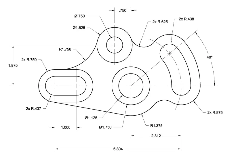
Hint

Use the CIRCLE and LINE command to get the following objects.
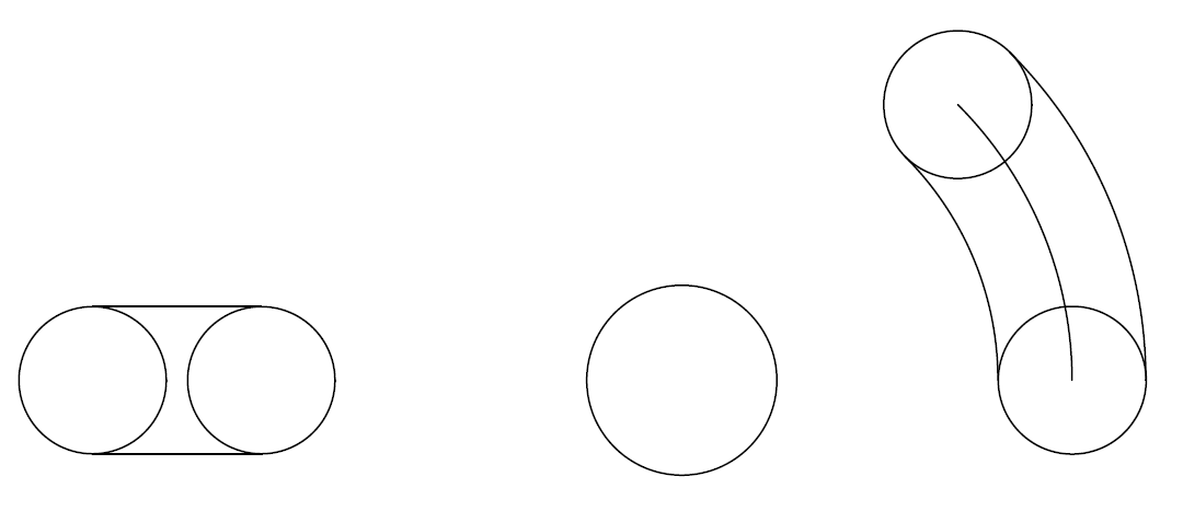
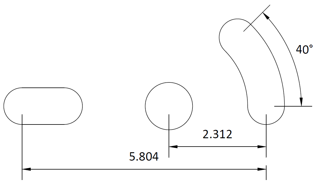
Clean it up using the TRIM command, you should have this
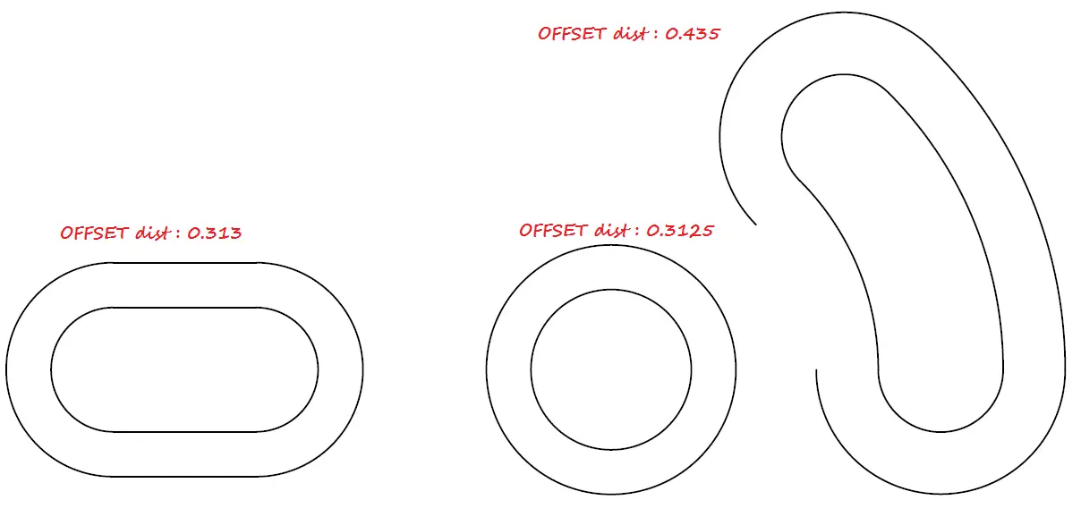
Use the OFFSET command to get the outer image of each block. You will need to find the appropriate OFFSET dimension for each block.
From this point on, you should be good to go, if you had some difficulties at the beginning of this session. With hope you had some difficult time today, I will love to see you in tomorrow 2D AutoCAD exercise session.
Don’t forget to like it this has been helpful.

[ws_table id=”3″]
Comments
19 responses to “20 Days of 2D AutoCAD exercises #17”
Using so small units is a bit problematic when using them as metric units. when applying centre lines to the drawing they look nothing like what they are in yours, is there something you can do to make the spaces between each dash of the centre line smaller to make it look like a proper centre line? Is it line type scale? I think you can do it for individual or group gripped objects but I cant find where to change the line type scale for the layer.which would make it easier than having to edit the centre lines when drawn if that makes sense!!
Right click in the drawing area, and select Options, Go on the Display tab, and try changing Display resolution.
Here is an image that can help you find it easily: Smoothen Display resolution in AutoCAD
Thanks for the reply, your solution sounds rather radical for something that I could have easily got wrong when I set my drawing units up, having looked and read a bit, I think it was the insertion scale I used when configuring my drawing units for my metric template, my unit type was decimal and my insertion scale was millimeters, so obviously when I am using the dimensions you are quoting on the exercise drawing its no wonder my centre lines looked like ordinary lines, having changed the insertion scale to cm, the lines look more like yours do, these exercises have been very good, I realise that you cant include all the information that a novice like me would need when it gets down to the finer details but used in conjunction with a more in depth book, the lessons are invaluable, the jargon in the book I am using (Mastering AutoCad) can get quite technical so the practical methods applied in these exercises helps to simplify some of the over complicated text in the book.
Thanks for sharing.
I did not know that that could solve the problem you were having. Nice to know!
Happy to know these exercises helped you, It is hard to include all information a novice need as you are mentioning in your comment, but asking questions could help improve these tutorial, and as a student you need to play with the software until figuring some others tricks out yourself.
Thanks for your participation.
You are definitely right, you have to just hit a few buttons and see what happens!! As an aside, I have been searching all over to try and find a clean method of inserting/exporting/embedding .dwg files into Microsoft Word/PowerPoint documents. I am a student and will be starting my HNC in Civil Engineering in September and will be given assignments where it would be much easier and simpler to place my drawings in Microsoft products, I thought it would be a simple as copy and past to clipboard but that does not seem to be the case. Do you know of any clean method to do this?
Thanks
You can print your project in TIFF, PNG or JPG files, and import the result to your Microsoft Word/powerpoint
Sorry, that doesn’t mean a lot to me, I have never printed anything more than a simple drawing, which I have configured to my Brother printer at home.
CTRL P, Standard A4 Portrait and Landscape setup, 1:1 scale, plot window, centre plot, do not have much idea as to how to print in TIFF< PNG or JPEG.
I have Publish to Web JPG/PNG but when I select either from the drop down options I get pop up, plotter configuration does not support the paper size of the current layout. What do you want to do/
Use default Paper Size Sun Hi Res 1600×1280 pixels
Use a custom paper size 2480×3507 pixels
Use a custom paper size and it it to the plotter configuration.
Everything I have read said it is wise to set drawing limits, would you recommend this? I kind of thought it was a means to reduce the load on your processor. With the Zoom Extents facility its kind of hard to gets bits of drawing lost.
Now I will say it depends on the type of image you are trying to export.
You might want to export your design to a better rendering software (most of them will read dwf files) and render it, After rendering, you will have a far better picture.
But if you are trying to export 2D images, the bigger your screen the better. I sometime use ‘WINDOWS’ (not LIMIT) while printing, and I will print it in the highest available resolution in a PDF format. This give me more control on the resulting image.
I’m getting confused, all I want to do is export my 2D drawings into Word/PowerPoint yet you are talking about printing, can we go through it step by step please, from when I have the finished 2D drawing and I want to place it in my Word document.
Thanks
Sorry for getting you confused! 😉 but printing in a PDF, PNG … means exporting images to those file’s type. If you have an image in a PDF, or PNG, or JPG, can’t you import it into your Word/PowerPoint?
I will try to write a short post on this topic and show you how I am doing it.
Hi there, I´m doing the exercise of day 17. The issue is that I want the
drawing to look the same as in the exercise. Everything is perfect so
far but how can I change the annotation for diameter to show only one
arrow at the circle instead of putting the circle between two arrows of the standard annotation?
Hi there, I’m a beginner and just started practicing on these drawings, I have completed all the objetcs according to dimensions given but im stuck on the arc which has a radius of 1.375 below the middle circle. I can’t seem to figure out how to draw it. Please help. Thanks
Hi, I was just finished this exercise. I guessed the R1.375 just above 2.312 is supposed to be the radius of another ‘invisible’ circle sharing the same center as the two circles above it (i.e. those with diameter 1.125 and 1.750). So in other words, you will need to create another circle with that center with radius of 1.375. Then you create a Line connecting the tangents of this circle and the ellipse on the left.
Another contour just right next to it would perhaps be created by tangent circle, similar to the rest of tangent arcs on the top portion of the shape.
Hope 4 months are not too late to get you back up to continue the exercise. 🙂
Just how the above 2 circles have radius of 1.750 and 1.125, and then the bigger outer invisible circle have a radius of 1.75
Just how the above 2 circles have radius of 1.750 and 1.125, and then the bigger outer invisible circle have a radius of 1.75 ???
Hi,
So judging by your comment, these exercises are in inches?.
And to use the metric system is better to make these numbers as cm and not mm?.
Thanks.
The smaller circles have a diameter of 1.75 and 1.125 (radii of .875 and .5625 respectively). The circle with a radius of 1.75 would has a larger diameter (3.5).
https://uploads.disquscdn.com/images/f8fcb8e98d221a7d3784531b50177861599492db7ce9fb9f4ce81c6e4d740bbf.png placement of the arc R1.750 is shown wrong it would start from end point of circle.