
After learning few important commands from Sketcher and Part Design workbench, we can now create a simple 3D part in CATIA. In this post the focus is learning how to use other commands like Hole, Edge Fillet.

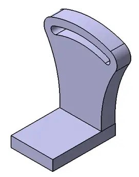
Here is the 3D object we will try replicating using CATIA.
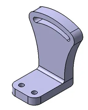
Lets dive right into it
Step 1
On the front plane draw a 2D sketch as shown below.
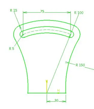
While creating this sketch we will need to use options like Cylindrical Elongated Hole, Three Point Arc, Line, Trim. If you are not familiar with these command in CATIA, you may need to have a look at how we lately create this simple 2D object in CATIA.
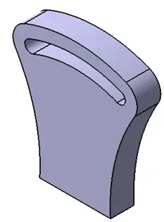
Extrude this sketch 20 mm using Pad command. We will get following object.
Step 2
Now select the top plane for sketching and draw the sketch given below.
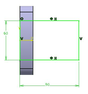
Extrude the sketch to 15 mm distance in the downward direction. We will get the object shown in following figure. Unlike AutoCAD, CATIA treats both extrudes as two features of a single part. Hence we do not have to use Boolean operations here. CATIA provides that option too, but we will learn Boolean operations in another tutorial. Now, the isometric view of the part looks like this
Step 3
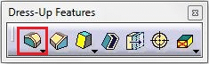
To obtain rounded chapes at the edges we are going to use Edge Fillet command. In the Dress-Up Features toolbar you will find Edge Fillet command.
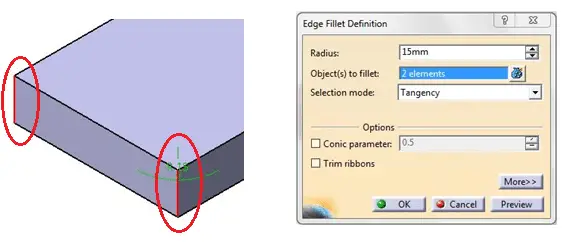
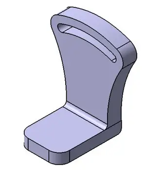
Similarly give edge fillet with appropriate radius to another two edges and we will get following object.
Step 4
Now, for creating the two holes we will not use Pocket option. Instead of that we are going to use Hole command. You will find this command in Sketch-Based Features toolbar.
To use a sketch based feature, we need a sketch. Similarly to create a hole we are required to define its centre point.
Using HOLE command
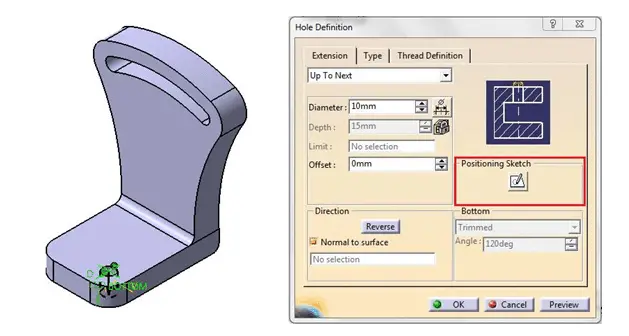
- Click Hole command. Hole Definition dialogue box will appear as shown.
- Now select the surface on which you want the hole. It will place the hole on that surface. But we need the hole at a proper location.
- See the dialogue box, there is an option called Positioning Sketch. This allows us to define location of hole. Click on the option and it will take you to the Sketcher workbench.
- Give proper dimensions to the point and click on Exit workbench.
- See the Preview, if the hole is at its required location then click OK.
Use same procedure to create another hole.
After following this procedure we will get our final component.
Few important things to remember
- One should avoid using commands like Chamfer and Corner while drawing a sketch, because that makes the sketch complicated. Instead of that, use Chamfer and Edge fillet commands from Part Design workbench.
- The sketch should be as simple as possible. This enables us to reedit the model easily.