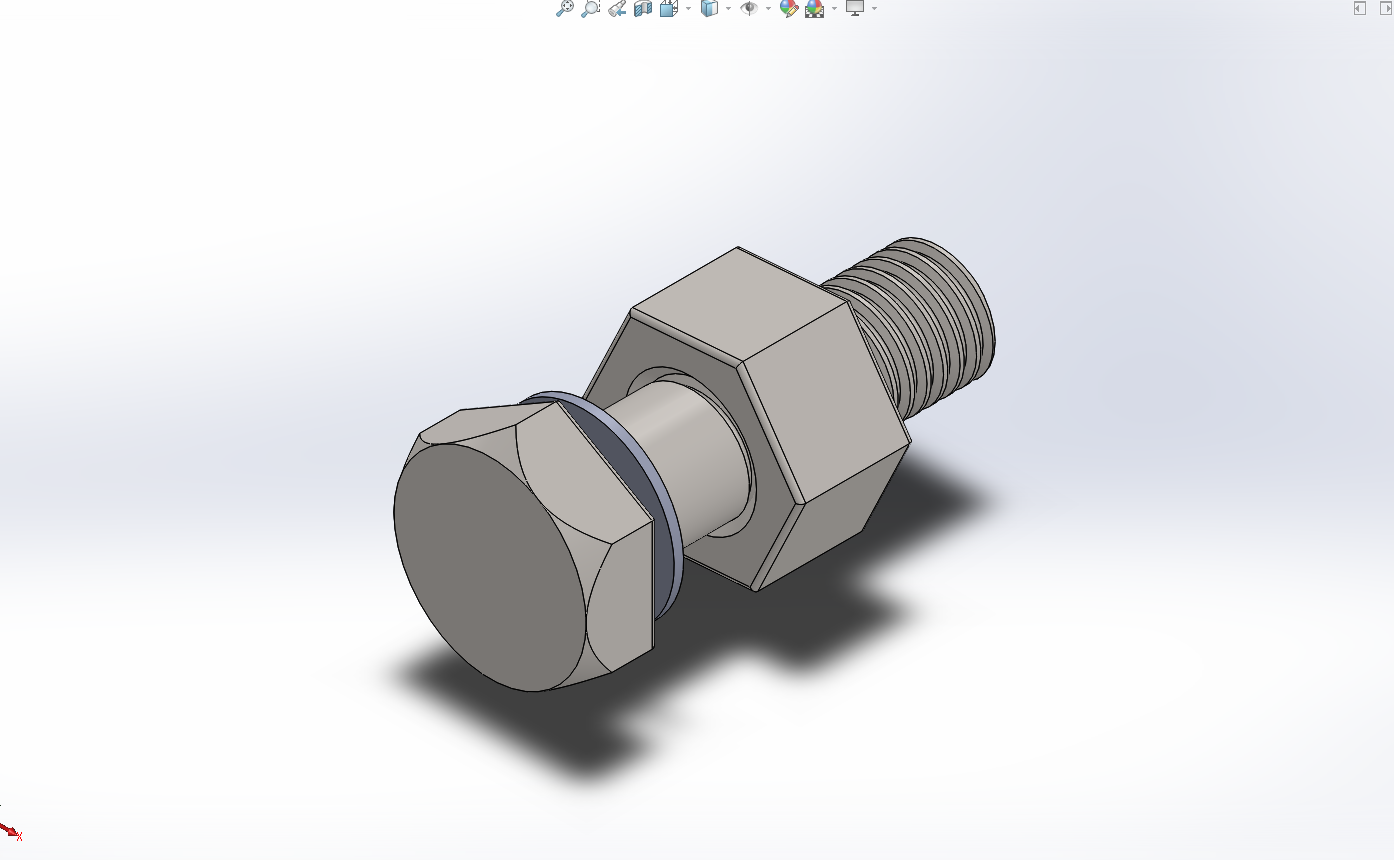
Production of drawing plans is the process in which the design is formally documented of a piece or set. SolidWorks contains a variety of tools that allow easy documenting of design documents, regardless of the phase in that is the process of production of plans. You can create drawing views associative parts and three-dimensional sets that can be updated quickly when the piece or the set change. These views are created in the “View Layout Bar”. The following assembly can be downloaded in here.
A combination of the above methods also offers the possibility of address the changing needs of the workflow. You can place a view of associative drawing that can be updated when the model changes. Then, if you want to make changes to the document without changing the model, you can convert the associative drawing view into a drawing view of 2D elements.

How to create a drawing from ASSEMBLE/PART:
It doesn’t matter if you’re in an assembly or in solidworks part screen. When you hit the window “file” an option called “Make drawing from part/assembly”. One you hit on that option, the screen will change to drafting in SolidWorks. The first window that will pop up is the sheet format/size window. There you choose the width and length of your worksheet, there are four different options but there’s an option to custom size the worksheet’s dimensions.
Once you choose your worksheet size, automatically SolidWorks will set up the options to draft and display the worksheet which can be later be modified as the designer’s or drawer’s demands.
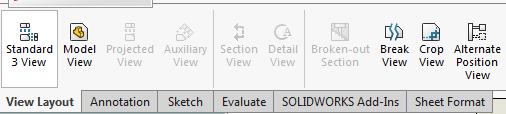
The main drafting tools that will be explained in this article will be in the “View Layout Window” which are:
- Standard 3 View
- Model View
- Projected View
- Auxiliary View
- Section View
- Detail View
- Broken-Out section View
- Break View
- Crop View
- Alternate Position View
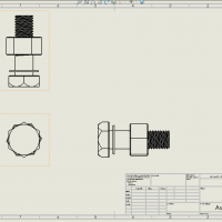
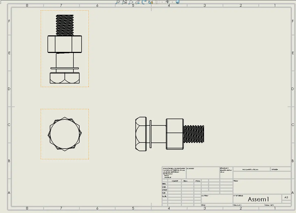
Standard 3 view
This is a kick off start tool when you start making drawing of your assembly. According to the plane and origin you design and draw your work piece. SolidWorks will pick three views which you could start adding dimensions, tolerances and notes. The orientations that SolidWorks will provide automatically would be the superior, front and right view as it is shown in the following picture.
Model View
This tool will allow you to choose and modify the orientation, size and appearance of the view you place on your worksheet. You can create multiple views of the following: isometric, front, back, left, right, top and bottom.
Also you can modify the display model to show it as a solid or as a drawing. The display model is really useful to show drill holes and internal guides/veins or internal cavities on work pieces or import annotations made in the 3D modeling.
Projected view
The projected view will help to create a new view starting from an existent one. Take a look at the following image as an example. The top view was chosen as a reference and with the cursor you can drag the orientation in the direction you want to change the view. A gray referenced line is created to indicate from which view you are projecting the new orientation. In this tool you can as well modify the display of the view.
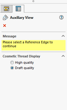
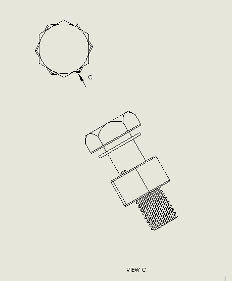
Auxiliary View
An auxiliary view requires you choose an edge of one of the views you already placed in the worksheet. Take a look at the following example in which one edge of the bolt’s head was chosen. SolidWorks automatically creates the view of the selected edge as you would see it in front and shows an arrow with a designated letter or number to make reference of the view.
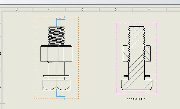
Section View
With this tool, you can make a section cut of a view. You can choose to make a horizontal or vertical cut. There are also options to customize and make a two points or three point section cut. Check the following image as an example of a vertical cut.
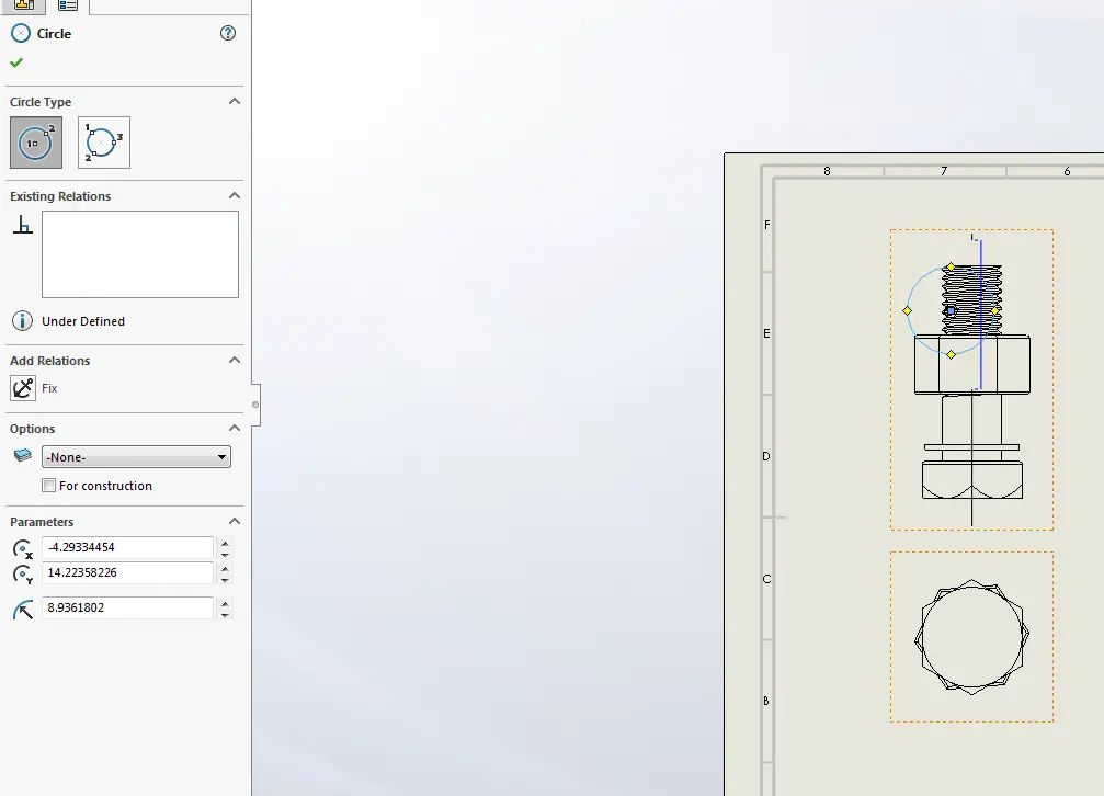
Detail View
A detail view is a simple zoom of an already existent view in your worksheet. The form of selection to zoom is by drawing a 2 point circle (center to diameter) or an ellipse using 3 points. Check the following picture as an example of a detail view in the bolt’s string.
Broken-Out Section
A broken-Out section view is made by drawing a spline across a section of interest in a work piece view on the worksheet. A chunk of section of the solid is taken out with tool. This view is really useful to display interior cavities of a solid piece.
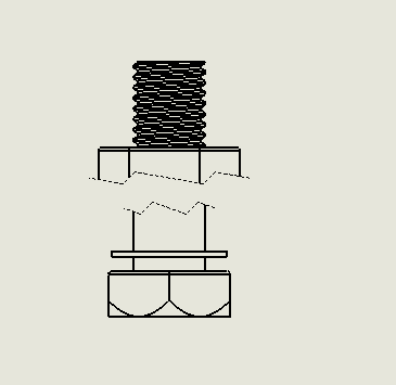
Break View
A break view will allow you to create a new view in which the new view will be cut according the direction and option you choose. You can make a horizontal or vertical cut with different types of break cuts.
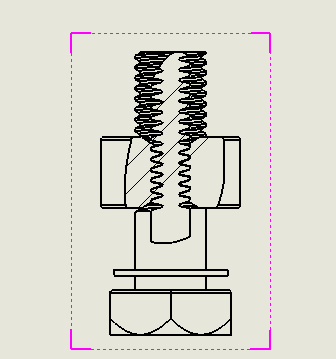
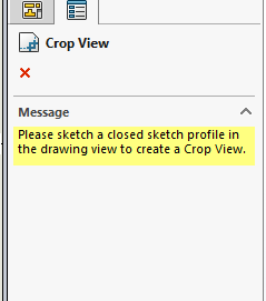
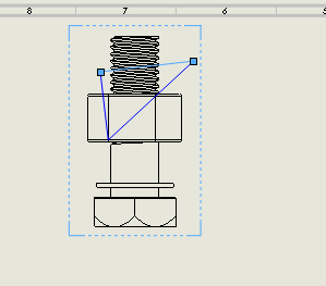
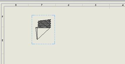
Crop View
In order to make a crop view. It is necessary to make a close sketch in an area of interest. Check the following example as a triangle is drawn to crop the view in only one area of interest.
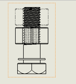
Alternate Position View
This tool is to superimpose one drawing view directly on top of another. The addition on the other view is displayed with phantom lines. Typically used to show the range of motion within an assembly. This tool is really useful when there’s an assembly that you need to show different positions. In this example, the nut is rotated to the top using a free drag rotation movement.
When you complete alternating the position of the nut, the standard view will automatically be modified and show the displacement of the nut in dotted lines.
Conclusions
The view layout tools are necessary to be able to display an orientation or a partial section view of a workpiece. In this article, all of the tools were revised separately. The intention to learn all of these tools is to be able to combine them and be able to illustrate in one drawing the necessary views for the manufacturer to comprehend and understand the workpiece.
Want more Solidworks? Check out our 10 Solidworks Furniture Design tips.