
Drawing a spring in AutoCAD is relatively easy using the SWEEP command. If you had a look at how I started working on AutoCAD 3D you would know a little about the SWEEP command.
But before getting to using the SWEEP command, I would like to go through a simple but primitive way to easily construct a 3D spring in AutoCAD.
what you will find here:

Creating a Spring in AutoCAD – Method 1
You can create a 3D spring in AutoCAD using two arcs forming a perfect circle. I explain.
Step 1
Draw a circle, cut it into two equal parts such as having something like shown in the image below
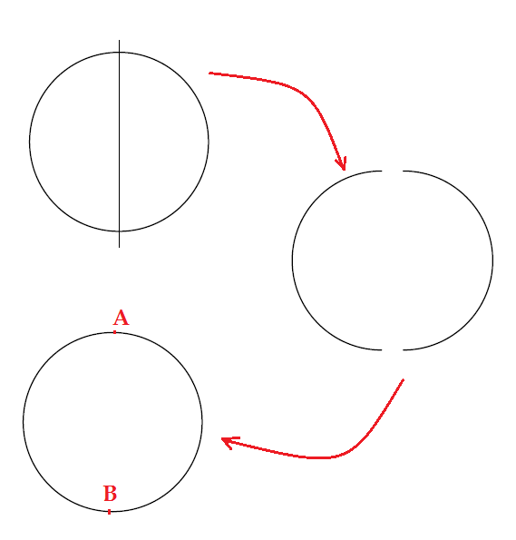
A and B are points where the two arcs meet.
Step 2
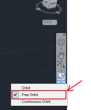
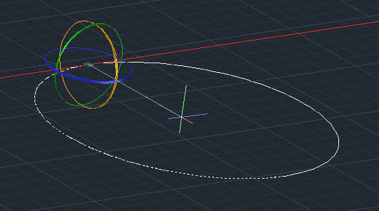
Now we are going to rotate an arc with 20 degrees and the other with -20 degrees around either A or B (You can take any angles you want but make sure the angles you choose are equal with opposite signs). You can use the FREE ORBIT to put the drawing in an isometric position and and use the 3D ROTATE to rotate arcs.
To use the 3D rotate command, click on 3D ROTATE, specify the rotation center, the plane of rotation and angles. (While using the 3D ROTATE you can rotate following x, y, or z planes, you need to select one of the colored circle shown in the figure below to indicate the plane of rotation. Following the example below, I will select the yellow circle)
You should be having a similar image while using the 3D ROTATE
Step 3
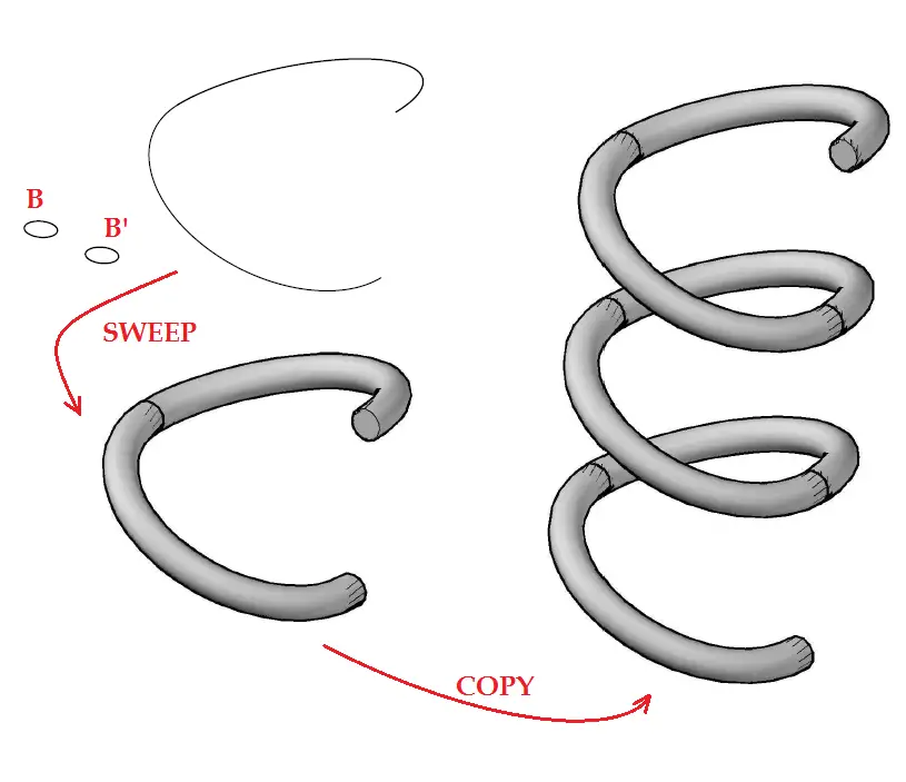
After Rotation, draw a circle and duplicate it. B and B’ are similar. Now use the SWEEP command on the first ARC with the circle B and do the same with B’ on the second ARC.
Now copy the first piece and stick the duplicated copy at the end of the original. You can repeat this as many time as wanted considering the height you want your spring to have.
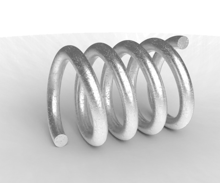
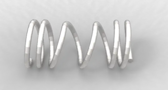
What I like in this technique is, you can easily change the rotation angle to get a not uniformly distributed turns along the spring, having a figure like the one below. At the end of your design, you may need to use the UNION command to join all pieces in such a way they form only a single spring.
Creating a Spring in AutoCAD – Method 2
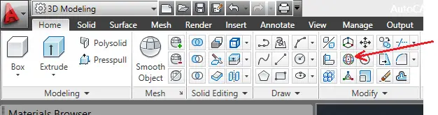
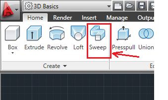
This is hassle free method. You simply need to use the HELIX command to get the path drawn. Draw the object to sweep (which is a circle in our example if you want to get a spring) and you are ready to use the SWEEP command the way we did above in step 2
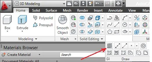
The image above shows the HELIX command.
To draw a Spring in AutoCAD using the HELIX command, you need to:
- Specify center point of base:
- Specify base radius or [Diameter] <1.0000>:
- Specify top radius or [Diameter] <291.5944>:
- Specify helix height or [Axis endpoint/Turns/turn Height/tWist] <1.0000>:
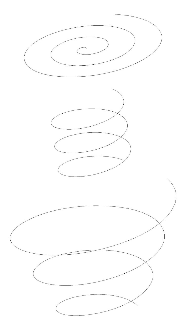
The images below show what you can achieve using the HELIX command in AutoCAD
On the first image, the top radius is bigger than the base radius, and the helix height is zero. it gives a sort of spiral.
On the second image, the top radius and the base radius are equal, the helix height is not zero.
On the third image, the top radius is bigger than the base radius, and the helix height is not zero.
While using the HELIX command on the 4th step, you can draw an Spring indicating, the number of turns, the turn height, the axis endpoint and the twist.
The Twist feature helps you have either a clockwise rotation or a counterclockwise rotation for your spring. The command windows looks like this when it is activated.
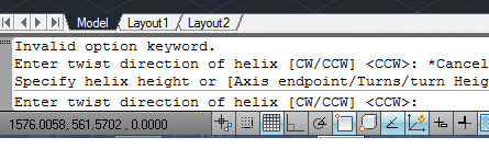
(by default the CCW is activated)
How to draw threaded rod in AutoCAD
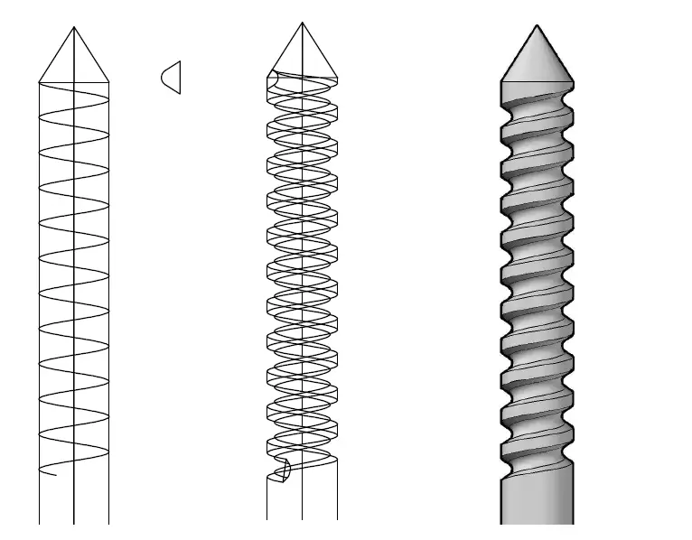
The same technique is used to draw threaded rod in AutoCAD. To draw threaded rod, you use the HELIX command.
In the following example, I used the HELIX command to draw a spring along the cylinder and I got the small triangle with rounded top to SWEEP around the spring. Then I used the SUBTRACT command to subtract the resulting object from the cylinder.
To draw the cylinder you, can use a figure like the one below. Use the REGION command to join all lines together to form a single object. (You may need to check what the REGION command does in AutoCAD) . Now use the REVOLVE command to revolve the whole around the red line to get the cylinder.
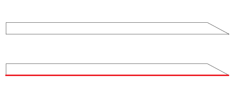
After the REVOLVE command, you get the image below.
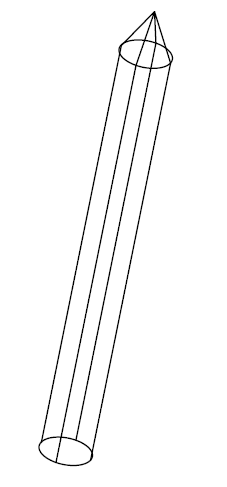
Switch to an isometric view to be able to design the spring around the cylinder. Remember you need to draw the small triangle in a 2D view.
Hope you learned something in this post, feel free to drop your concern in the comment section below, I will be pleased to give further information in case you feel like I went too fast in some steps.