What does it make you think of? Create your first peace of 3D in AutoCAD. Yea, I used to be so excited about 3D objects, specially when I will see a user exploring all sides of the object and be able to rotate it, zoom in and out.
Here is a Step by Step 3D AutoCAD for beginners that will help you understand when and how to use certain basic command in AutoCAD.
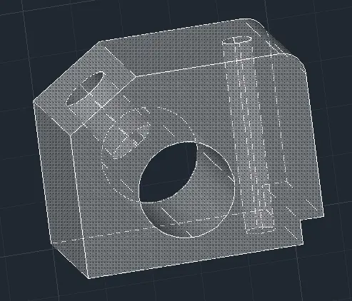
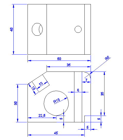
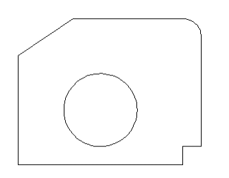
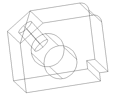
These are for you to understand what we are aiming to design using AutoCAD . You have 2 2D views and the 3D view below. I have tried to provide all information about dimensions.

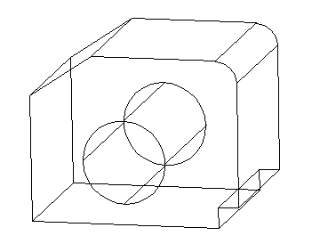
Here below is the 3D image of our exercise.
Step 1
Get the figure below using dimensions stated above. The tricky part may be to get the circle at its exact position. You might want to check how to use the Quadrant feature of Osnap in AutoCAD to be able to draw the circle outside and move it to its right position or you can simply do the math and find out where the center of the circle is going to be (knowing its radius and how far it is situated from the base of our main figure)
Step 2
Find the REGION command to transform our lines to a block.
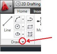
To find the REGION command, Click on the small arrow beside Draw to pull down the menu
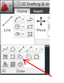
Select the REGION command and select the whole figure (every lines should be selected), then press ENTER on your keyboard. Actually, you just need to select the outer figure without selecting the circle, but it makes no difference if you decide to select everything.
Step 3
Find the EXTRUDE command and select it.
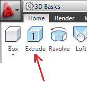
Select everything, type 40 on your keyboard and press ENTER. You should get the figure below.
Step 4
What we need now is subtracting the volume 2 from the volume 1.
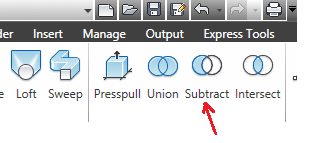
Select the SUBTRACT command, an subtract the cylinder 2 from the figure 1. You might want to check how to use the SUBTRACT command in AutoCAD if you are not familiar with this command.

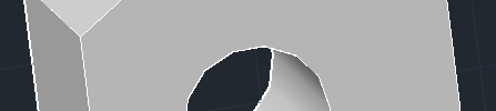
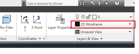
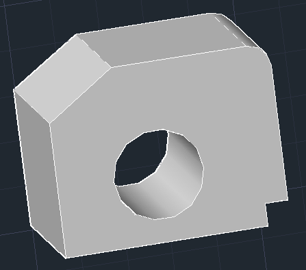
To notice the result of the SUBTRACT command and see how it affected your design, change the VISUAL STYLE from 2D Wireframe to Shades of grey to get the result below.
Step 5
Get on our previous VISUAL STYLE, and draw a Diagonal like shown on the figure below.
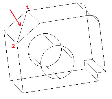
Make sure to allow the DYNAMIC UCS
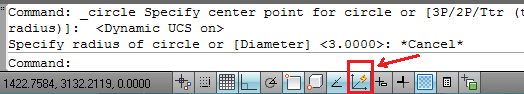
Star a circle at the center of the diagonal and set the radius to 10.
Step 6
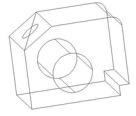
Use the EXTRUDE command like in Step 3 to get a cylinder of height 10. (you can extrude with a negative value to see the difference, try with -10)
In my case the Cylinder grew outward when I wanted it to grow inward. So I will use the MOVE command to change the position of my cylinder such as having it like this. (To move your cylinder, use the center of the outer base of the cylinder as the first base point of displacement, and the center of the diagonal as the second point)
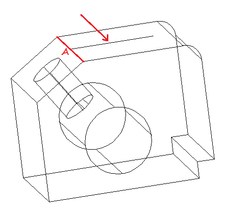
Draw a line of 25 from the center of the segment A. Make sure ORTHO Mode is allowed to be able to draw a straight line perpendicular to A.
Step 8
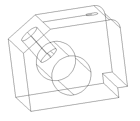
Use the center of our line to draw a circle of radius 3.
Step 9
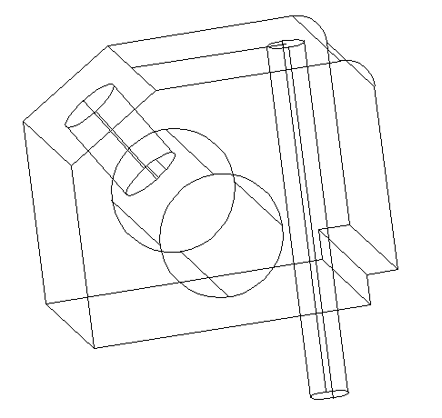
Use the EXTRUDE command to get a cylinder from the circle we have just drawn, and make sure the cylinder is longer than the main object like shown on the figure below.
Step 10
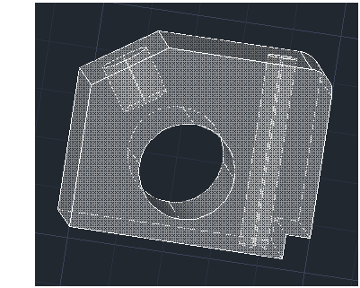
Use the SUBTRACT command, and subtract the last two cylinders from the main figure and you should be done with the exercise.
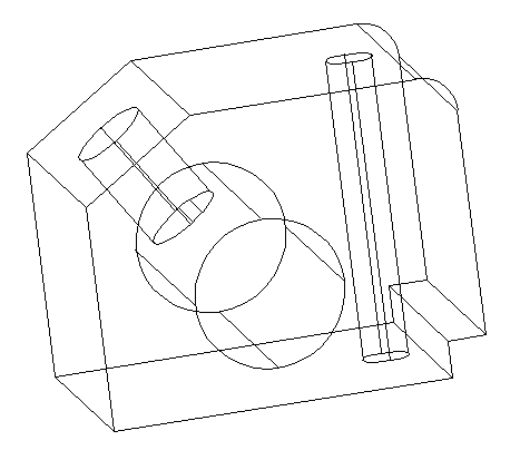
You should get the figure below while changing the VISUAL STYLE to X-Ray