
 In the world of CAD, coordinates play a part as important as any other. Any rotation, skewing or other manipulation is done with the help of mathematical equations and the help of regular geometric and algebraic techniques that work with the coordinates. For this purpose, the inherent nature of coordinates and the subsequent introduction of coordinate systems is of little surprise or debate. With AutoCAD and some other CAD products, the coordinates are divided into two systems. The World Coordinate System (WCS) and the User Coordinate System (UCS). Read on for more information about the two.
What is WCS?
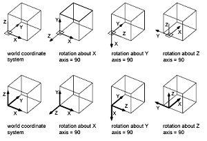
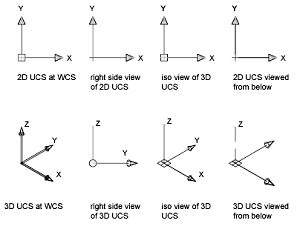
The WCS is a coordinate system that is fixed throughout your CADing activities. This is so that the package has a default system that it can refer to when manipulating your objects, adding new elements and doing the rest of the things you ask of it. Like the UCS, it hosts the X and Y axis in 2D and the additional Z-axis in 3D.

What is UCS?
The UCS as mentioned is a user-defined coordinate system. This is the one that is moveable and can be manipulated by the user. This is because you need a dynamic coordinate system that gets updated in real-time for your cad proceedings to actually get realized. This is where the WCS and the UCS differ. The UCS is relative to the user and the model/project, whereas the WCS is fixed for your CAD’s internal mechanics.
Behind the Scenes
 In a new project, the WCS and the UCS are the same. They are aligned for you to have a standardized view of the drawing canvas from the start. This means that the UCS is calibrated in accordance with the WCS and when you change its orientation or manipulate it in any way, you are basically recalibrating it according to the WCS.
For a deeper understanding, take the X-Y plane only. Leaving out the Z-axis we have a two dimensional surface or plane that we will create new objects on. Here, a system element or variable called “Elevation” will determine where you elements are drawn. If the elevation is 0, the element will get drawn on the plane, whereas a positive value of elevation will draw the element on top of the plane. The negative value will draw below.
Many CAD packages allow you to create your own UCS along with the default one available. The new and default UCS can be deleted, whereas the WCS cannot be manipulated by the user at all. These coordinate systems define the following:
- The x-y plane, also called the work plane.
- The “horizontal” & “vertical” directions relative to your drawing.
- Alignment options for objects, elements and other canvas based parts.
- Origins for rotation and size manipulation
The UCS in AutoCAD allows you to reposition it and even align to objects, if you want to set the whole drawing relative to that element.
Working with the UCS
Commands
The following commands are available in AutoCAD for working with the UCS.
UCS
Manages the UCS and offers further options for its setup.
UCSICON
As the command name suggests, it toggles the visibility of the icon and other visual properties
UCSMAN
This tool helps manage the extra systems that a user has defined. Same as UCS command for your CSs.
A Few Things to Keep in Mind
 Having more than one UCS can be cumbersome. Keeping the following in mind will help with your CADing. First off, all UCS commands will reference the UCS in use. So with multiple UCS, you have to be using the UCS to issue a command to it. At any point in time, if you lose direction or orientation, you can do one of two things.
First you can restore a saved UCS, if you have saved one that is. It will load in its default position and will set your drawing to the stated orientation if you tell it to. The other way is for you to recalibrate your UCS in accordance with the WCS. This will align your UCS/model/drawing to the original or default orientation.
If you have multiple objects or complicated drawings, setting the UCS at its origin is the best thing to do because not only will you always be able to refer to it and set the original orientation of the canvas, you would get a clear understanding of your own drawing because the whole project will line up according to the default work plane.
The DDUCSP command has preset templates relative to the WCS. In the case, you need to set elevations according to the WCS, these presets will help you switch to a default orientation without hassle. For this command to work effectively, always select the “Absolute to WCS” option. Lastly, always save your drawings with the UCS aligned to the WCS. This will help avoid confusion next time you open your drawing.
Conclusion
The coordinate system is without a doubt, one of the foundation pillars on which all CAD systems stand. Using a coordinate system allows you to calibrate and align all your drawn elements all the while allowing you to have a standard and fixed point of reference to fall back on when things, quite literally, get out of hand.